Panoramic tooth trauma camera shooting locator

A locator and trauma technology, which is applied in the field of medical devices, can solve the problems of difficulty, inconvenience, and easy to twist the head during the camera process, and achieve the effect of fast camera process.

Active Publication Date: 2020-08-11
马学梅
View PDF10 Cites 4 Cited by
  • Summary
  • Abstract
  • Description
  • Claims
  • Application Information

AI Technical Summary

Problems solved by technology

[0004] The purpose of the present invention is to solve the problem that the fixed structure of the existing locator is not easy to adjust, making it inconvenient to take pictures of patients of different heights, and the patients tend to twist their heads during the process of taking pictures, which makes the process of taking pictures difficult and very inconvenient disadvantages, and proposed a panoramic tooth trauma camera localizer

Method used


Image

  • Panoramic tooth trauma camera shooting locator
  • Panoramic tooth trauma camera shooting locator
  • Panoramic tooth trauma camera shooting locator

Examples


Embodiment 1

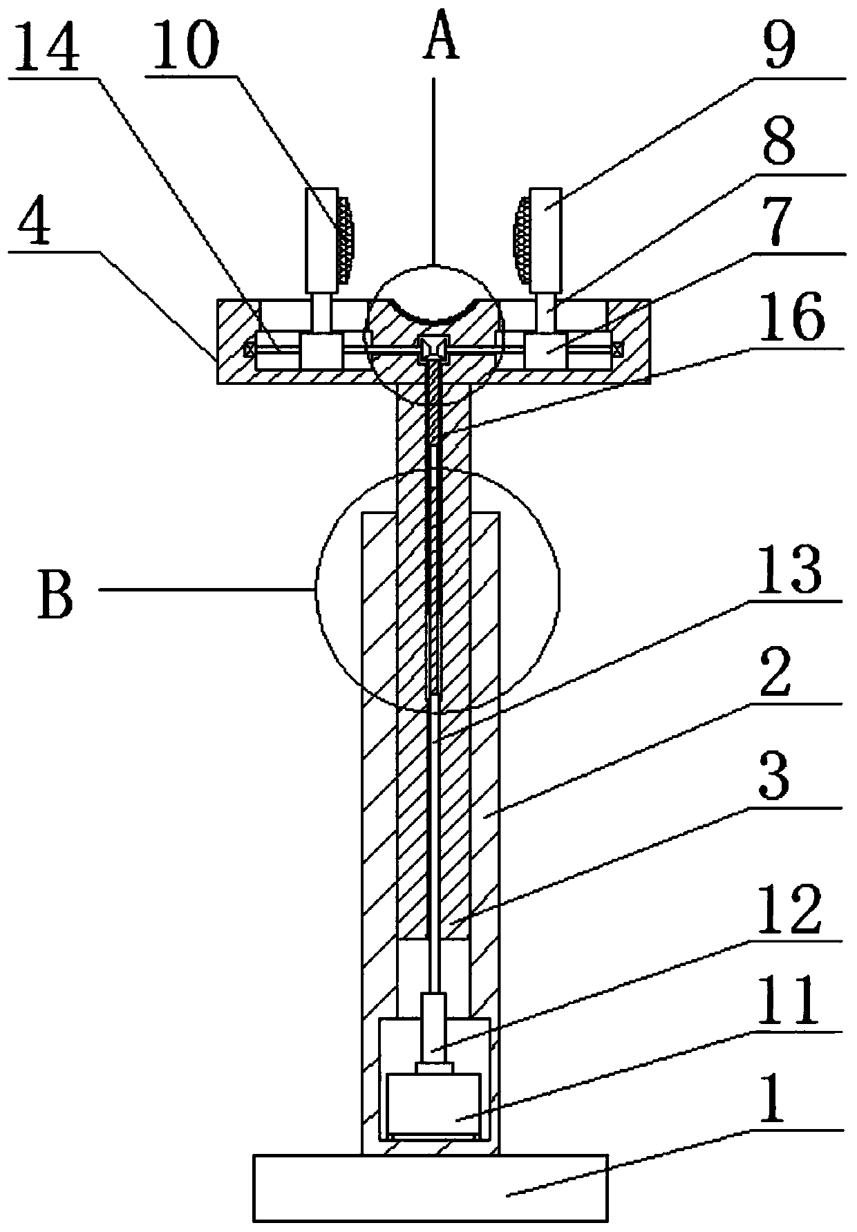
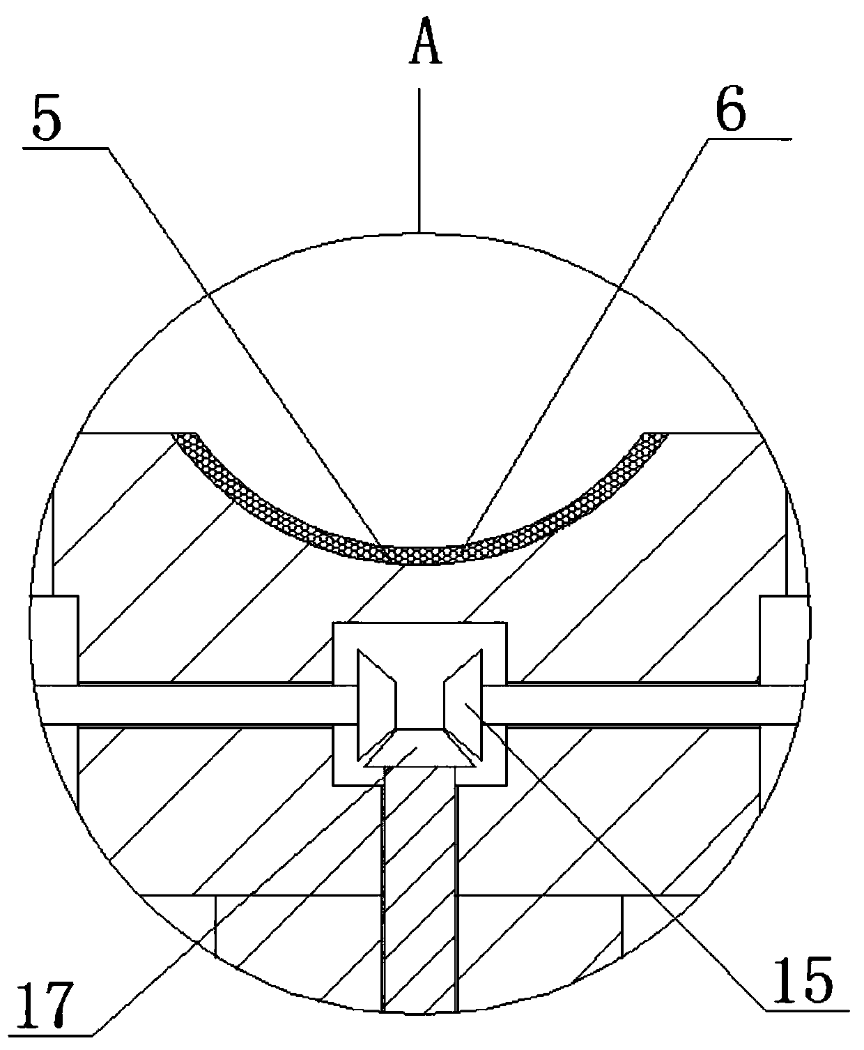
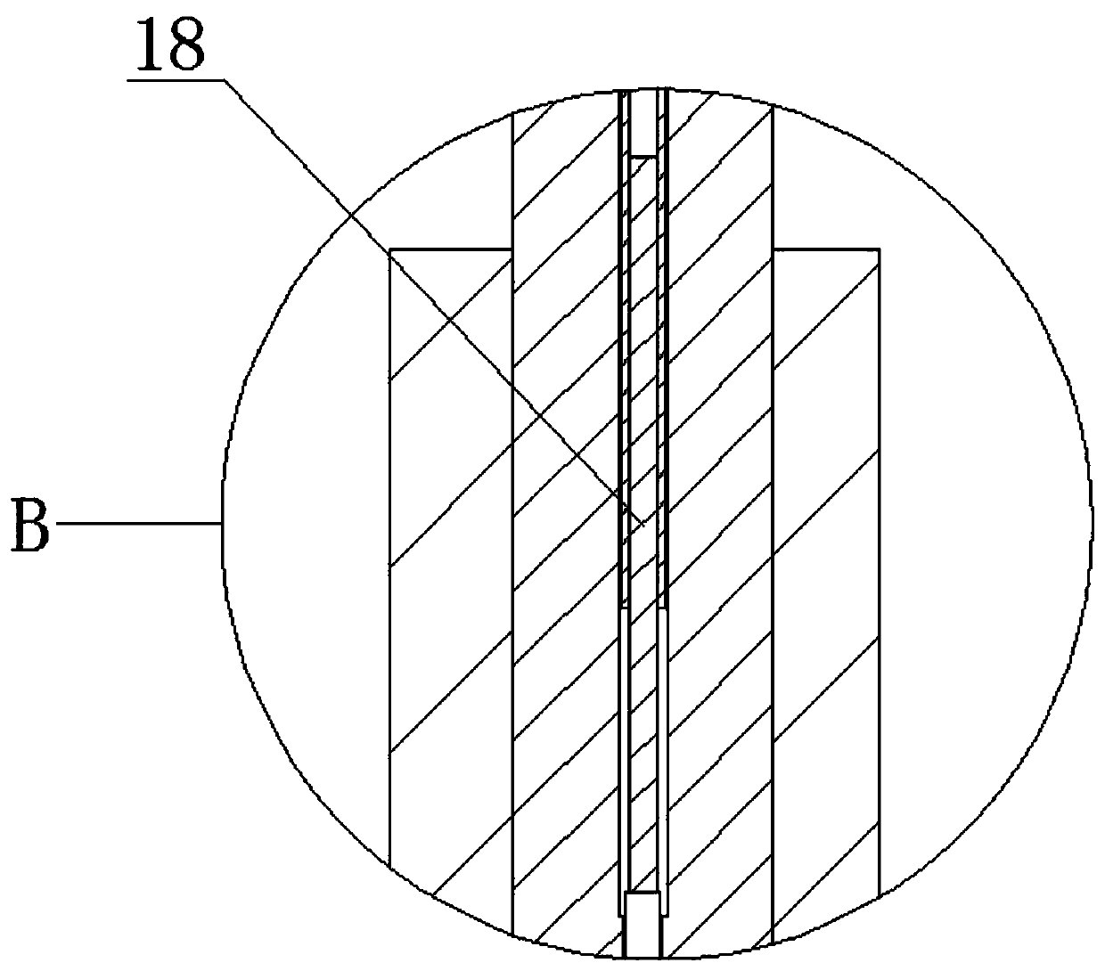
[0021] refer to Figure 1-3 , a panoramic tooth trauma camera positioner, comprising a base plate 1, the top of the base plate 1 is fixedly connected with a support column 2, the top of the support column 2 is provided with a first rectangular chute, and a rectangular support rod is slidably installed in the first rectangular chute 3. The top of the rectangular support rod 3 is fixedly connected with a positioning block 4, and the top of the positioning block 4 is provided with a placement groove 5, and the placement groove 5 is provided with a protective pad 6, and the top of the positioning block 4 is provided with two slideways, and the positioning The block 4 is respectively provided with a slide block groove connected with the two slideways, and a slide bar 7 is slidably installed in the two slideways, and a slide block 8 is slidably installed in the two slide block grooves, and the two slide bars 7 One end of the two sliders respectively extends into the grooves and is f...

Embodiment 2

[0027] refer to Figure 1-3 , a panoramic tooth trauma camera positioner, comprising a base plate 1, the top of the base plate 1 is fixedly connected with a support column 2 by welding, the top of the support column 2 is provided with a first rectangular chute, and a rectangular chute is slidably installed in the first rectangular chute. Support rod 3, the top of rectangular support rod 3 is fixedly connected with positioning block 4 by welding, and the top of positioning block 4 is provided with placement groove 5, and placement groove 5 is provided with protective pad 6, and the top of positioning block 4 is provided with two slides. and the positioning block 4 is respectively provided with slider grooves connected with the two slideways, the slide bar 7 is slidably installed in the two slideways, and the slider 8 is slidably installed in the two slider grooves. One end of each slide bar 7 extends into the two slide block grooves and is fixedly connected with the tops of the...


PUM


Abstract

The invention belongs to the technical field of medical devices, particularly relates to a panoramic tooth trauma camera shooting locator, and aims to solve the problems that the patients with different heights cannot be conveniently shot due to the fact that the existing locator is inconvenient to adjust due to fixed structure, the camera shooting process is relatively difficult and particularlyinconvenient due to the fact that the patient is easy to twist a head in the camera shooting process. The following scheme is now proposed, the locator comprises a bottom plate, the top of the bottomplate is fixedly connected with a supporting column, a first rectangular sliding chute is formed in the top end of the supporting column, a rectangular supporting rod is arranged in the first rectangular sliding chute in a sliding mode, the top end of the rectangular supporting rod is fixedly connected with a locating block, and a placing groove is formed in the top of the locating block. By arranging fixed plates and the rectangular supporting rod, the locator is convenient to shoot the patients with different heights, and the patient is not likely to twist the head in the camera shooting process, so that the camera shooting process is rapid and particularly convenient.

Description

technical field [0001] The invention relates to the technical field of medical devices, in particular to a panoramic dental trauma camera positioner. Background technique [0002] In people's daily life, teeth are often damaged due to eating habits or other factors. It is necessary to go to the hospital for panoramic dental trauma photography so that doctors can formulate a reasonable treatment plan. When taking panoramic photography of patients' teeth, it is necessary The patient's head is fixed by a positioner so that the doctor can take pictures; [0003] However, the existing locators are often fixed in structure and inconvenient to adjust, making it inconvenient to take pictures of patients of different heights, and patients tend to twist their heads during the process of taking pictures, making the process of taking pictures difficult and very inconvenient. Contents of the invention [0004] The purpose of the present invention is to solve the problem that the fixed...

Claims


Application Information

Patent Timeline
Patent Type & Authority Applications(China)
IPC IPC(8): A61B90/14A61B5/00
CPCA61B90/14A61B5/70A61B5/0088
Inventor 马学梅张恒德张恒健
Owner 马学梅
Why Eureka
Try Eureka