Cooling pipe and cooling structure of mold

A technology of cooling structure and cooling pipe, applied in the field of cooling structure, can solve the problems of leakage of cooling fluid, easy separation or distortion of O-rings, inability to increase the extrusion margin, etc. Twist or break away, the effect of simplifying work

Inactive Publication Date: 2019-04-19
株式会社阿雷斯提
View PDF9 Cites 4 Cited by
  • Summary
  • Abstract
  • Description
  • Claims
  • Application Information

AI Technical Summary

Problems solved by technology

In the technology disclosed in Patent Document 2, although it is not as cumbersome to fasten the thread when installing the cooling pipe to the cooling hole, when the cooling pipe is inserted, the O-ring is easy

Method used


Image

  • Cooling pipe and cooling structure of mold
  • Cooling pipe and cooling structure of mold
  • Cooling pipe and cooling structure of mold

Examples


Embodiment Construction

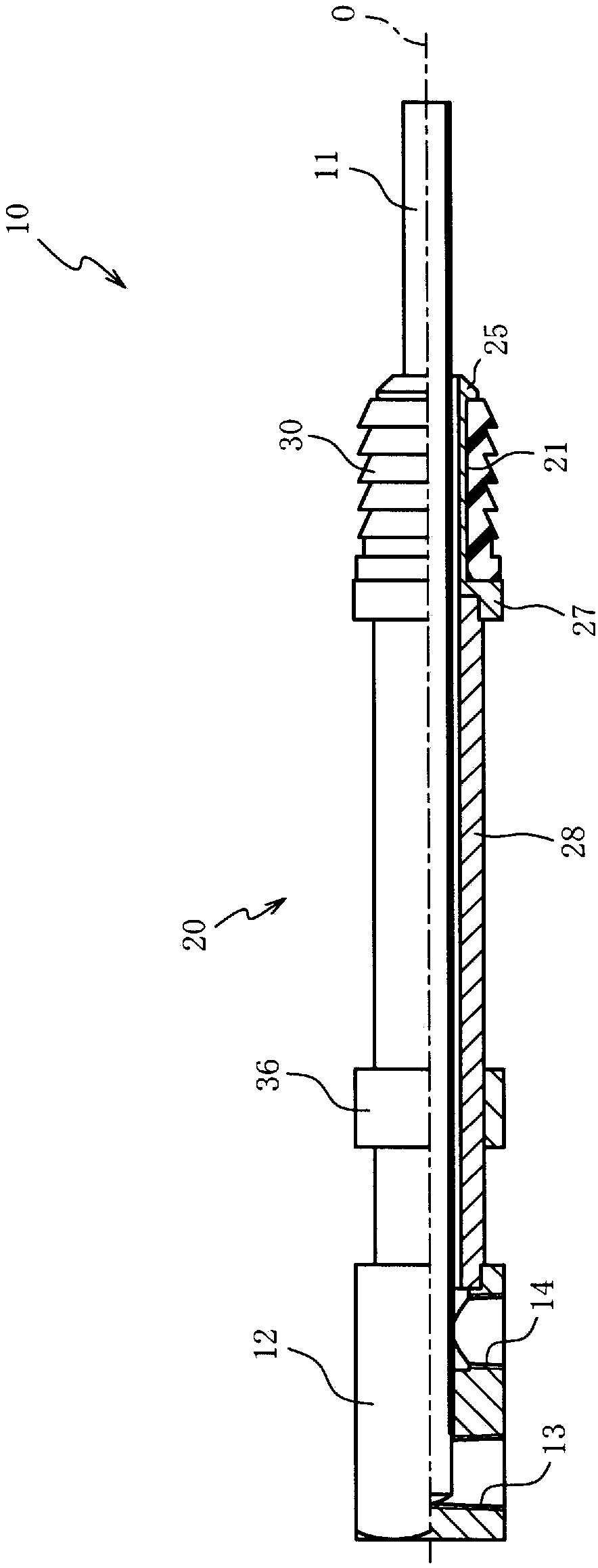
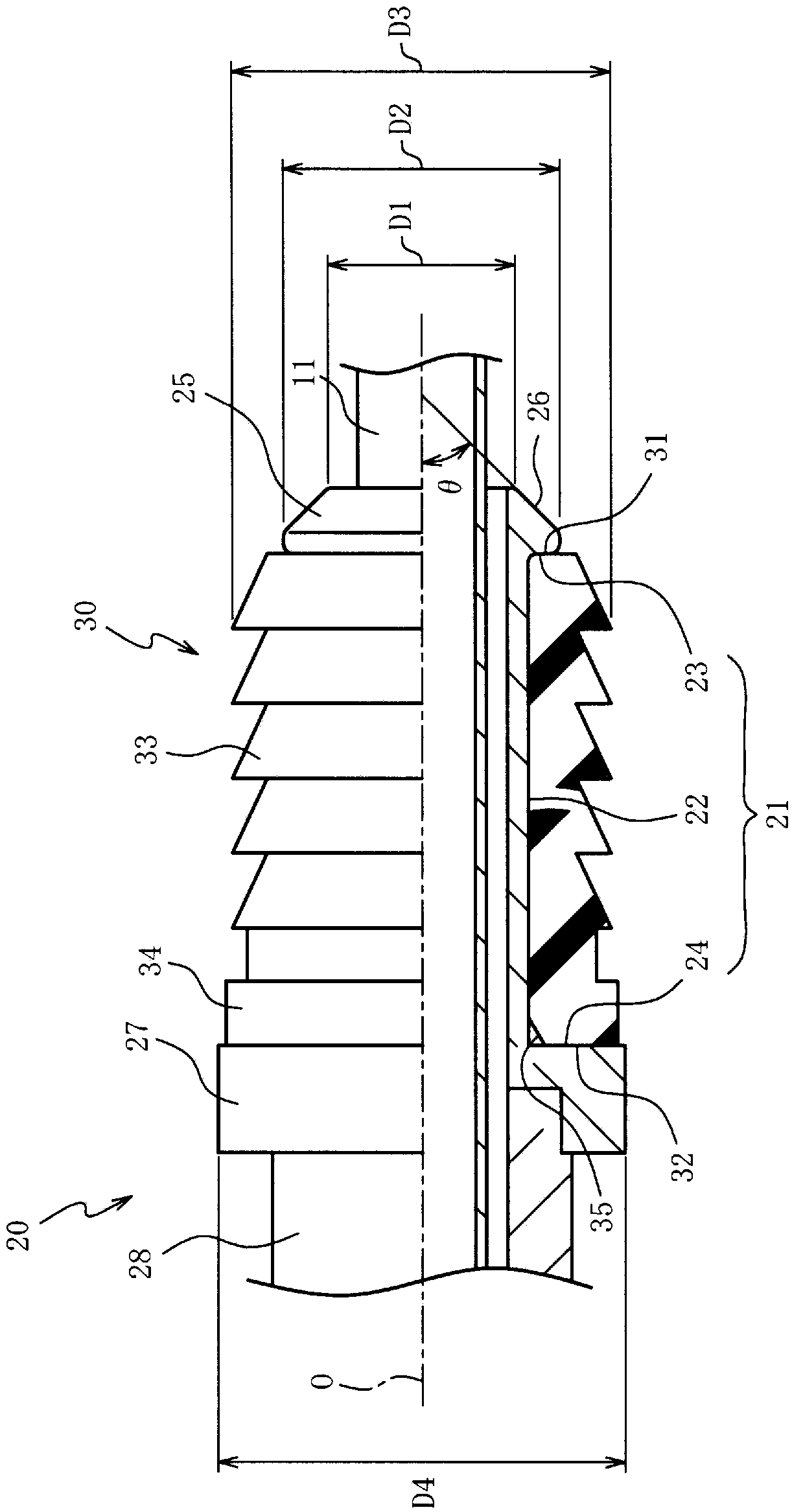
[0030] Hereinafter, preferred embodiments of the present invention will be described with reference to the drawings. figure 1 It is a half cross-sectional view with the axis O of the cooling pipe 10 as the boundary in the first embodiment of the present invention, figure 2 It is an enlarged half cross-sectional view of the front end side of the cooling pipe 10. in figure 1 with figure 2 In, half of the full cross-sectional view of the cooling pipe 10 and half of the outline view are shown sandwiching the axis O ( Figure 3 to Figure 5 Same as in). in figure 1 with figure 2 In the figure, the right side of the figure is called the front end side of the cooling pipe 10, and the left side of the figure is called the rear end side of the cooling pipe 10 ( Figure 3 to Figure 5 Same as in).

[0031] Such as figure 1 As shown, the cooling pipe 10 includes: a first pipe 11 extending from the front end side to the rear end side along the axis O; the first pipe 11 is surrounded by a g...


PUM


Abstract

The invention provides a cooling pipe and a cooling structure of a mold. Operation for mounting into a cooling hole can be simplified, and meanwhile leakage of cooling fluid is not prone to happening.The cooling pipe inserted into the cooling hole formed in the mold comprises a pipe and a lip packing, wherein the pipe extends from the front end side to the rear end side along the axis, a groove recessed towards the inner side in the axis right-angle direction orthogonal to the axis is formed in the outer circumference, and the lip packing is arranged on the outer side in the axis right-angledirection of the bottom surface of the groove formed in the pipe; the groove has a first face facing the front end surface of the lip packing and a second face facing the rear end surface of the lip packing, the pipe is provided with a first portion and a second portion, a first face is formed at the rear end, a second face is formed at the front end, and the outer diameter of the outer peripheralsurface of the first portion is enlarged from the front end side to the rear end side.

Description

Technical field [0001] The present invention relates to a cooling structure of a cooling pipe and a mold, and in particular to a cooling structure of a cooling pipe and a mold that can simplify the work of mounting to a cooling hole. Background technique [0002] As a cooling structure of a mold for manufacturing a molded body by pressure casting, injection molding, etc., a structure is known that supplies a cooling fluid from a cooling pipe installed in a cooling hole formed in a mold to a cooling hole (Patent Documents 1 and 2). In order to prevent the cooling fluid from leaking from the cooling hole, in Patent Document 1, the cooling pipe is fastened to the cooling hole by screws, and in Patent Document 2, an O-ring mounted on the cooling pipe is interposed between the cooling pipe and the cooling hole. [0003] Prior art literature [0004] Patent literature [0005] Patent Document 1: Japanese Patent Application Publication No. 2004-154796 [0006] Patent Document 2: Japanese Pat...

Claims


Application Information

Patent Timeline
IPC IPC(8): B29C45/73B22D17/22B29C33/04
CPCB22D17/2218B29C33/04B29C45/7312
Inventor 高桥贵美隆
Owner 株式会社阿雷斯提
Why Eureka
Try Eureka