Parallel rod type forging manipulator lifting mechanism with slantly-arranged pitching linear actuator

A linear drive, forging manipulator technology, applied in forging/pressing/hammering machinery, manufacturing tools, forging/pressing/hammer devices, etc., can solve the problem that the gripping capacity of the manipulator is not large and the range of force changes is large. , the parallelism of lifting is reduced, etc., to achieve the effect of high pitching motion transmission efficiency, strong overall bearing capacity, and simplified structure

Inactive Publication Date: 2013-04-24
YANSHAN UNIV
View PDF6 Cites 10 Cited by
  • Summary
  • Abstract
  • Description
  • Claims
  • Application Information

AI Technical Summary

Problems solved by technology

Among them, the parallel link type forging manipulator has high motion decoupling and is easy to control. If the synchronization rod of the parallel link type forging manipulator is placed at the top, it can reduce the force on the hinge joint of the frame, but most of the synchronous The rod top parallel link type forging manipulator only contains a single pitching hydraulic cylinder, such as Chinese patents 201010543863.5, 201010133714.1, etc. The manipulator clamping c

Method used


Image

  • Parallel rod type forging manipulator lifting mechanism with slantly-arranged pitching linear actuator

Examples


Embodiment Construction

[0008] The embodiments of the present invention are described in detail below in conjunction with the accompanying drawings: this embodiment is implemented on the premise of the technical solution of the present invention, and detailed implementation methods and specific operating procedures are provided, but the protection scope of the present invention is not limited to the following the described embodiment.

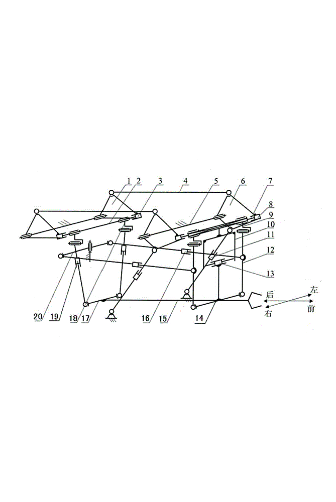
[0009] figure 1 The hoisting mechanism of the parallel link type forging manipulator with tilting linear drive tilted as shown includes a hoisting device, a swinging device, front and rear buffer devices, left and right buffering devices and a frame. 15 is installed on the hoisting device bottom, and the front end of the front and rear buffering devices is connected in the front suspension rod 12 middle part of the lifting device, and the rear end is connected with the frame 5, and the left and right buffering devices are installed between two front suspension rods 12...


PUM


Abstract

The invention discloses a parallel rod type forging manipulator lifting mechanism with a slantly-arranged pitching linear actuator. The lifting mechanism comprises a lifting device, a swing device, a front-back-left-right shock absorber, a claw beam and a frame, the front portion of the claw beam is connected with the lower ends of two forward mounting rods, the upper ends of the two forward mounting rods are connected onto a front sliding rod through connection pieces, a left linear actuator and a right linear actuator are arranged at two ends of a front-back sliding rod and, a front-back actuator is connected with a front-back lifting arm, and the other end of the front-back lifting arm is connected with the frame. Lower arms of two front lifting arms are connected with upper ends of two lifting linear actuators, upper arms of the front lifting arms are connected with the front ends of a horizontal synchronization rod, and the back end of the synchronization rod is connected with an upper arm of a back lifting arm. The lifting mechanism is characterized in that the back portion of the claw beam is connected with two slantly-arranged pitching linear actuators, the upper ends of the slantly-arranged pitching linear actuators are connected onto the back sliding rod through connection pieces. The parallel rod type forging manipulator lifting mechanism is high in pitching motion transmission efficiency, small in stress at frame hinging connection positions, strong in whole bearing capacity of the manipulator, simple in structure, and prone to guarantee lifting parallelism degree of the claw beam.

Description

technical field [0001] The invention relates to a forging manipulator of a free forging hydraulic unit, in particular to its lifting mechanism. Background technique [0002] As an important auxiliary equipment of free forging hydraulic unit, forging manipulator plays a vital role in improving the forging quality of forging and the production efficiency of unit equipment. Generally speaking, the forging manipulator needs to realize seven forging operation functions including jaw clamping, tong bar rotation, tong bar lifting, tong bar pitching, tong bar lateral movement, tong bar swing, and cart travel. Among them, the three actions of jaw clamping, clamp rod rotation, and cart walking are independent from each other in structure, and are respectively driven by motors or hydraulic cylinders. The clamp realizes the clamping and rotating functions of the workpiece, and the cart undertakes the traveling function. The action is realized by the lifting mechanism. At present, ther...

Claims


Application Information

Patent Timeline
IPC IPC(8): B21J13/10
Inventor 许允斗刘宇赵永生
Owner YANSHAN UNIV
Why Eureka
Try Eureka