
Silicon oil filling machine

A technology of filling machine and silicone oil, applied in liquid distribution, special distribution device, packaging, etc., can solve the problems of waste of silicone oil, long time required, inaccurate filling amount, etc.

Active Publication Date: 2014-07-16
济南易恒技术有限公司
View PDF6 Cites 0 Cited by
  • Summary
  • Abstract
  • Description
  • Claims
  • Application Information

AI Technical Summary

Problems solved by technology

[0003] The current oil injection method is to process two process holes on the corresponding parts of the crankshaft shock absorber, one oil inlet hole, one oil outlet hole, manual filling, silicone oil is injected through the oil inlet hole, and the oil outlet hole is discharged, and then welded after filling. Two wells, not only takes a long time (about a day), but also the amount of filling is not accurate
Since the viscosity of silicone oil is very high (100,000-600,000cps), and the oil injection process hole of the crankshaft damper is small, the conventional oil injection method takes a long time to fill, the filling quality cannot be guaranteed, and it will also cause waste of silicone oil

Method used


Image

  • Silicon oil filling machine
  • Silicon oil filling machine
  • Silicon oil filling machine

Examples


Embodiment Construction

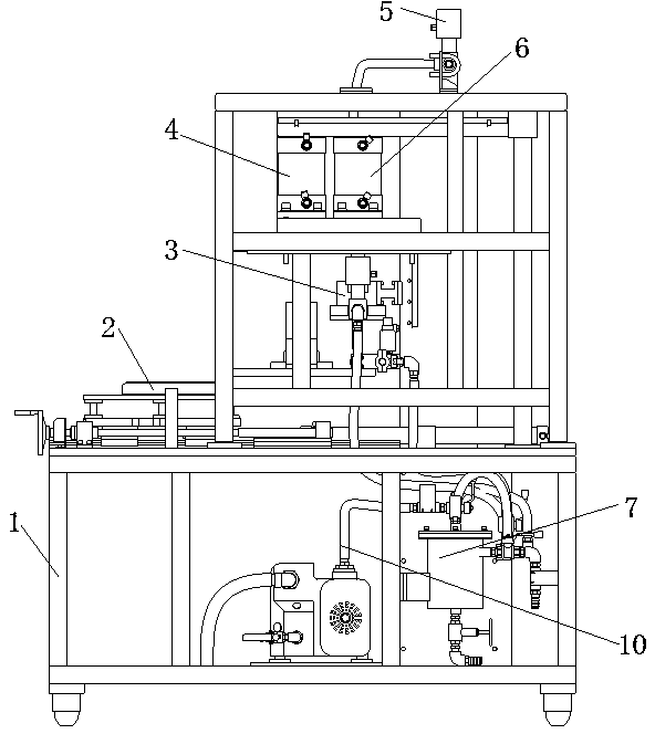
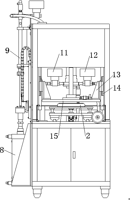
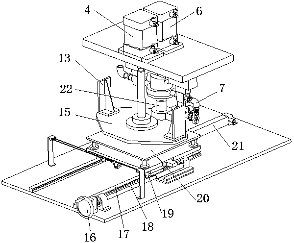
[0018] Such as figure 1 and figure 2 As shown, the structure of the silicone oil filling machine of the present invention mainly includes a frame 1, a positioning device 2, an oil supply device, a filling mechanism 3, a suction cleaning device and a vacuum pipeline. The positioning device 2, the oil supply device, the filling mechanism 3, the back suction cleaning device and the vacuum pipeline are all arranged on the frame 1, the filling mechanism 3 is located above the positioning device 2, and the filling mechanism 3 is connected with the oil supply device, the back suction cleaning The device is connected to the vacuum line. One end of the vacuum pipeline is connected with a vacuum pump 10 . The positioning device 2 is used for placement, movement and positioning of the crankshaft damper. The oil supply device is used for the delivery of silicone oil. The vacuum pump 10 and the vacuum pipeline are used to extract the air in the silicone oil shock absorber. Filling me...


PUM


Abstract

The invention provides a silicon oil filling machine which comprises a framework, a positioning device, an oil supply device, a filling mechanism, a vacuum pipeline and a suction cleaning device. The positioning device, the oil supply device, the filling mechanism, the vacuum pipeline and the suction cleaning device are arranged on the framework, the filling mechanism is positioned above the positioning device and is connected with the oil supply device, the vacuum pipeline and the suction cleaning device, and the suction cleaning device is connected with the vacuum pipeline. The positioning device is used for accommodating, shifting and positioning a crankshaft vibration damper. The oil supply device is used for delivering silicon oil. The filling mechanism is used for filling the silicon oil into the crankshaft vibration damper. The suction cleaning device is used for recycling redundant silicon oil. The silicon oil filling machine has the advantages that the silicon oil is filled into the crankshaft vibration damper in vacuum-pumping and then quantitative pressure filling modes, only one technical hole is required, the silicon oil is accurately filled via a quantitative cylinder in the vacuum-pumping filling mode, the silicon oil filling machine is high in automation degree and accurate in filling quantity, and the technological difficult problem in the aspect of filling silicon oil into crankshaft vibration dampers is solved.

Description

technical field [0001] The invention relates to a device for filling silicone oil to a crankshaft damper, and belongs to the technical field of silicone oil filling. Background technique [0002] A shock absorber is usually installed at the front end of the crankshaft of the engine. As a torsional vibration damping device of the high-speed engine, it plays a decisive role in the running stability of the high-speed engine. In order to ensure the long-term operation of the crankshaft damper, silicone oil is filled in it through the oil injection process hole on the crankshaft damper. [0003] The current oil injection method is to process two process holes on the corresponding parts of the crankshaft shock absorber, one oil inlet hole, one oil outlet hole, manual filling, silicone oil is injected through the oil inlet hole, and the oil outlet hole is discharged, and then welded after filling. It takes a long time (about one day) to make two holes, and the amount of filling i...

Claims


Application Information

Patent Timeline
Patent Type & Authority Patents(China)
IPC IPC(8): B67D99/00
Inventor 郑云同王志忠李东谢乡华甄雪峰
Owner 济南易恒技术有限公司
Learn More