Connection joint between basement base plate and underground diaphragm wall

An underground diaphragm wall and basement floor technology, applied in the field of building component nodes, can solve the problems of reducing the bearing capacity of the diaphragm wall, reducing the thickness of the diaphragm wall, increasing the force of the steel plate, etc., achieving good force transmission performance and impermeability performance, reducing Bend Anchor Welding, Effect of Increased Strength and Rigidity

Active Publication Date: 2013-04-24
广东省建科建筑设计院有限公司
View PDF6 Cites 8 Cited by
  • Summary
  • Abstract
  • Description
  • Claims
  • Application Information

AI Technical Summary

Problems solved by technology

These two methods require relatively accurate positioning, but it is difficult to ensure accurate positioning in the construction of the underground diaphragm wall; because the construction of the underground diaphragm wall is usually before the main construction drawing is issued, therefore, the reinforcement of the bottom plate is uncertain. The method of pre-embedded steel plate can consider the allowable construction error of the construction specification, which is more flexible
[0004] There are two methods of pre-embedded steel plates. The first is to embed the joint box in the diaphragm wall, and the bottom plate steel bar is welded with the pre-embedded steel plate in the joint box. Reduce the thickness of the diaphragm wall and reduce the bearing capacity of the diaphragm wall; the second method is that the steel plate is directly embedded on the surface of the diaphragm wall, and the bottom plate reinforcement is welded on the steel plate. However, in the case of small spacing and large number of reinforcement bars, all The steel bars are all welded on the steel plate to increase the stress on the steel plate. Once the thickness of the steel plate is insufficient, shear failure will easily occur; in addition, when welding, the steel bars need to be bent and anchored on the steel plate. Because there are too many steel bars, the spacing is small , difficult to weld

Method used


Image

  • Connection joint between basement base plate and underground diaphragm wall
  • Connection joint between basement base plate and underground diaphragm wall
  • Connection joint between basement base plate and underground diaphragm wall

Examples


Embodiment Construction

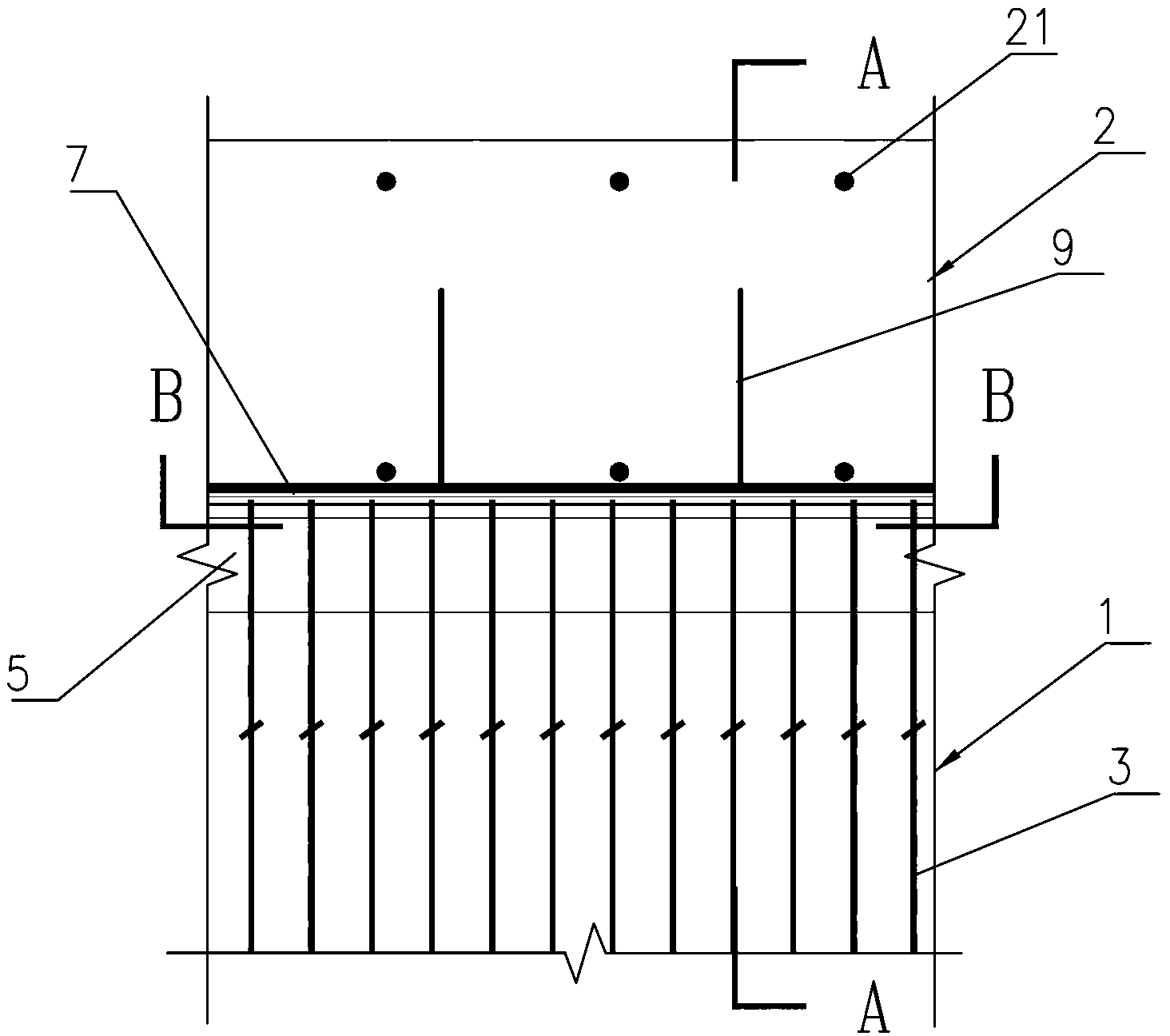
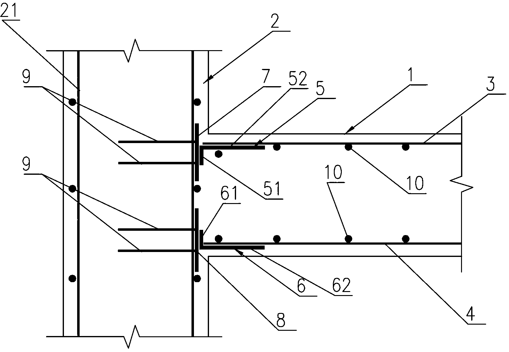
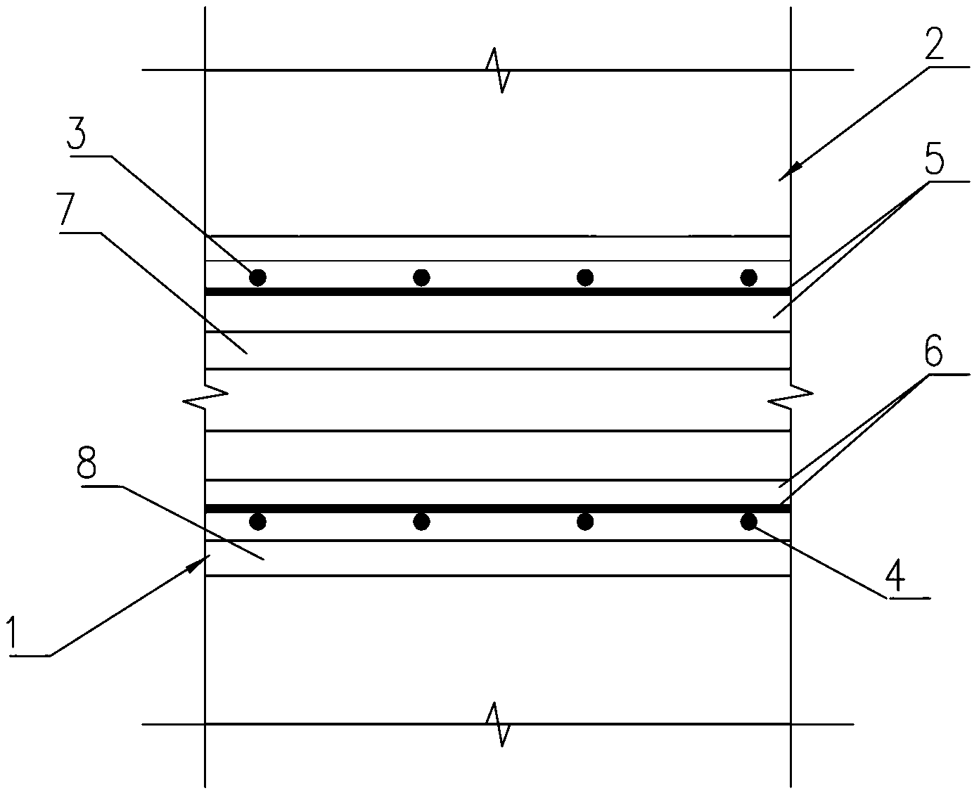
[0026] Such as Figure 1~3 As shown, it is a connection node between the basement floor and the underground diaphragm wall of the present invention, which includes a transition piece, and the transition piece is used to be arranged between the basement floor 1 and the steel plate on the inner surface of the underground diaphragm wall 2, and the underground diaphragm wall 2 It is the same wall as the outer wall of the basement, and the transitional connector is a long profile extending along the length direction of the underground diaphragm wall. For the underground diaphragm wall 2 , the plate surface of the steel plate is connected to its corresponding connection surface, and the transverse reinforcement is extended to the corresponding connection surface to be fixed.

[0027] In this embodiment, the transition connector adopts angle steel, and the transverse reinforcement is composed of the transverse gluten bar 3 located at the top of the basement floor 1 and the transverse...


PUM


Abstract

The invention discloses a connection joint between a basement base plate and an underground diaphragm wall. The connection joint comprises a transition connection component for being arranged between the basement base plate and a steel plate on the inner surface of the underground diaphragm wall. The underground diaphragm wall and an outer wall of the basement are the same wall. The transition connection component which is a long profile extends along the length direction of the underground diaphragm wall and is provided with connection faces corresponding to the steel plate and transverse reinforcements of the basement base plate respectively. The transverse reinforcements are perpendicular to the underground diaphragm wall, the steel plate surface is connected with the corresponding connection face, and the transverse reinforcements extend onto the corresponding connection face to be fixed. By means of the connection joint, on the premise that the prior bearing capacity of the underground diaphragm wall is guaranteed, the bending resistance and the shearing resistance between the basement base plate and the underground diaphragm wall are enhanced, the joint wholeness can be guaranteed, and the strength and the rigidity of the joint are improved effectively, so that the joint is provided with good force transmission performance and impervious performance.

Description

technical field [0001] The invention relates to a building component node, in particular to a connection node between a basement floor and an underground continuous wall. Background technique [0002] The underground diaphragm wall is a continuous wall constructed below the ground for water cut-off, anti-seepage, soil retaining, and load-bearing. At present, in the construction field, the phenomenon that the underground diaphragm wall and the basement exterior wall are combined into one is more and more common, and the connection methods between the underground diaphragm wall and the basement floor are also various. It is basically divided into three types, one is pre-embedded steel plates, and the bottom plate steel bars are welded on the steel plates; The steel bar connector is buried, and the bottom plate steel bar is connected to the connector. [0003] The method of using pre-embedded steel bars or pre-embedded steel bar connectors is applicable to the construction of...

Claims


Application Information

Patent Timeline
Patent Type & Authority Applications(China)
IPC IPC(8): E02D29/045E02D29/16
Inventor 徐其功陈春晖邝立智曹大燕邓建强
Owner 广东省建科建筑设计院有限公司
Why Eureka
Try Eureka