
Oil well pump

A technology for oil well pumps and pump barrels, which is applied in the field of oil well pumps controlled by double valves. It can solve the problems of steam lock, opening and closing delay of oil well pumps with fixed valve balls, low pump efficiency and mechanical recovery efficiency of heavy oil, and improve pump efficiency. and mechanical mining efficiency, and solve the effect of opening and closing lag

Inactive Publication Date: 2013-04-24
SHAANXI ZHONGMING ENERGY INVESTMENT
View PDF0 Cites 6 Cited by
  • Summary
  • Abstract
  • Description
  • Claims
  • Application Information

AI Technical Summary

Problems solved by technology

However, due to the viscosity of heavy oil in the process of thermal recovery, there is a hysteresis and steam lock phenomenon in the opening and closing of the oil well pump with the fixed valve ball, resulting in low thermal recovery pump efficiency and mechanical recovery efficiency of heavy oil.
In order to meet the needs of heavy oil production, some oil production plants have successively introduced streamlined oil well pumps, two-way oil inlet heavy pumps, forced opening and closing mechanical valve oil well pumps, and intrusive heavy oil pumps for thermal recovery of heavy oil. Properly solve the problems existing in the process of heavy oil exploitation

Method used


Image

  • Oil well pump

Examples


Embodiment Construction

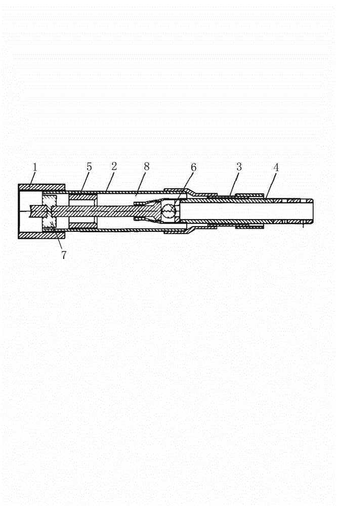
[0008] An oil well pump according to the present invention comprises a pump head 1, a pump barrel 2 and a plunger barrel 3, the pump head 1 is fixedly arranged at one end of the pump barrel 2, and the plunger barrel 3 is fixedly arranged at the other end of the pump barrel 2, And a part of the plunger barrel 3 extends to the inside of the pump barrel 2, the plunger rod 4 is movably arranged inside the plunger barrel 3, and the inside of the pump barrel 2 is also fixedly provided with a floating valve body 5, and the floating valve body 5 is set Between the plunger barrel 3 and the pump head 1, it is characterized in that the plunger rod 4 extends from the inside of the plunger barrel 3 to the inside of the pump barrel 2 and passes through the floating valve body 5. On the plunger rod 4 A fixed valve 6 and a floating valve cover 7 are respectively provided, the floating valve cover 7 is matched with the floating valve body 5, and the fixed valve 6 is arranged inside the plunger ...


PUM


Abstract

The invention discloses an oil well pump controlled by two valves. The oil well pump comprises a pump head, a pump cylinder and a plunger cylinder. The pump head is fixed at one end of the pump cylinder; the plunger cylinder is fixed at the other end of the pump cylinder, and a part of the plunger cylinder extends to the interior of the pump cylinder; a plunger rod is movably arranged in the plunger cylinder; a travelling valve is further fixed in the pump cylinder and arranged between the plunger cylinder and the pump head; the plunger rod extends to the interior of the pump cylinder through the interior of the plunger cylinder and penetrates through the travelling valve; and a fixed valve and a travelling bonnet are arranged on the plunger rod respectively, the travelling bonnet is matched with the travelling valve, and the fixed vale is arranged in the plunger cylinder. By means of the oil well pump, the problems of the vapor lock and the start and stop lag of the oil well pump and a fixed valve ball are solved effectively, and the pump efficiency and the mechanical extraction efficiency of thickened oil pumping are improved.

Description

technical field [0001] The invention relates to an oil pumping device, in particular to an oil pump controlled by double valves. Background technique [0002] The application of thermal recovery technology in heavy oil blocks has better solved the problem of heavy oil recovery. However, due to the viscosity of heavy oil in the process of thermal recovery, there is a hysteresis and steam lock phenomenon in the opening and closing of the oil well pump with the fixed valve ball, resulting in low thermal recovery pump efficiency and mechanical recovery efficiency of heavy oil. In order to meet the needs of heavy oil production, some oil production plants have successively introduced streamlined oil well pumps, two-way oil inlet heavy pumps, forced opening and closing mechanical valve oil well pumps, and intrusive heavy oil pumps for thermal recovery of heavy oil. It can well solve the problems existing in the process of heavy oil exploitation. Contents of the invention [00...

Claims


Application Information

Patent Timeline
IPC IPC(8): F04B47/00F04B49/22
Inventor 王梅玫
Owner SHAANXI ZHONGMING ENERGY INVESTMENT
Learn More