Fan impeller

A fan impeller and wheel cover technology, applied in the direction of mechanical equipment, machines/engines, liquid fuel engines, etc., can solve the problems of strength reduction, weight reduction, and accident increase, and achieve the effect of reducing power and weight

Active Publication Date: 2013-04-24
宁风科技(宁波)有限公司
View PDF8 Cites 11 Cited by
  • Summary
  • Abstract
  • Description
  • Claims
  • Application Information

AI Technical Summary

Problems solved by technology

[0004]But we know the hazards of fan accidents. Thinning the thickness of the impeller will inevitably lead to a decrease in the strength of the original impeller, which increases the possibility of accidents! Therefore, the purpose of reducing weight cannot be achieved simply by reducing the thickness of the impeller plate!

Method used


Image

  • Fan impeller
  • Fan impeller
  • Fan impeller

Examples


Embodiment 1

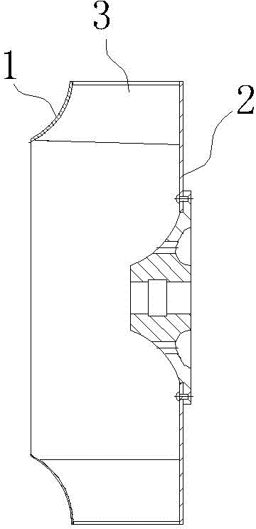
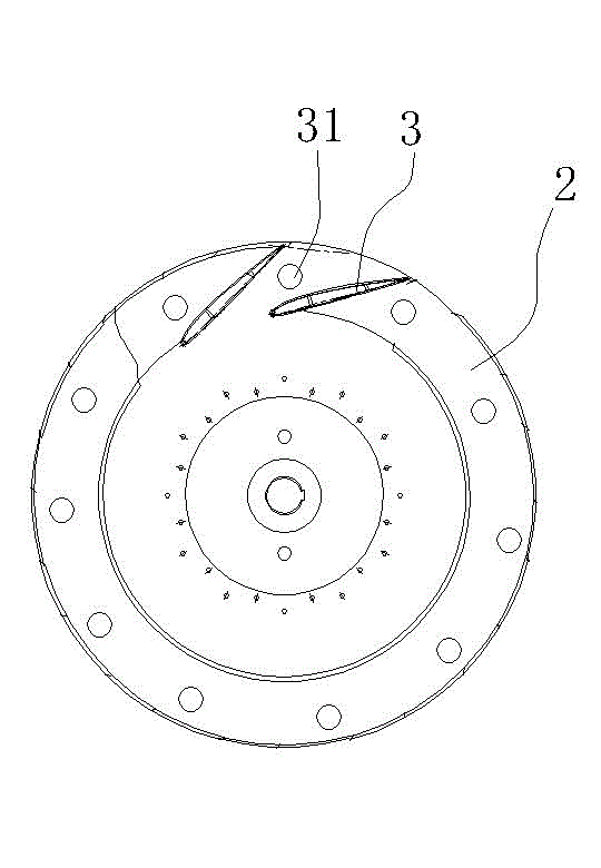
[0018] A fan impeller, comprising a wheel cover 1 and a wheel disc 2, the wheel cover 1 and the wheel disc 2 are connected together through blades 3, and the wheel disc 3 is provided with a number of evenly distributed holes for lightening the wheel The opening of the disc 3 weights.

[0019] The above-mentioned opening is a hole 31 arranged in the middle of the wheel disc 3, and a hole 31 is arranged between every two adjacent blades 3, and the area of ​​each hole 31 is the same. In this embodiment, its shape is The hole 31 is circular, and the position of the hole 31 is based on the premise that the position of the center of gravity of the wheel is not affected.

Embodiment 2

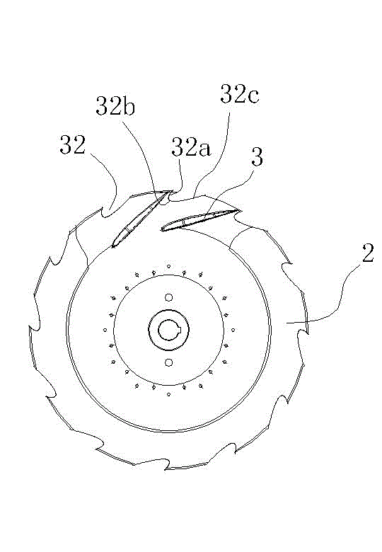
[0021] A fan impeller, including a wheel cover 1 and a wheel disc 2, the wheel cover 1 and the wheel disc 2 are connected together through blades 3, and the feature is that: the wheel disc 3 is provided with a number of evenly distributed blades for An opening for reducing the weight of the wheel disc 3 .

[0022] The above-mentioned opening is a gap 32 arranged at the edge of the wheel disc 3, and there is a gap 32 between every two adjacent blades 3, and the gap 32 gradually shrinks from the outside to the inside, and the opening direction Consistent with the direction of rotation of the impeller. Similarly, the shape and size of each notch 32 are the same, and its position is also based on the premise that the position of the center of gravity of the wheel is not affected.

[0023] Specifically in this embodiment, the edge of the notch 32 is in the shape of a "hook" arc, which includes a first arc segment 32a close to the end of the blade 3, a second arc segment 32c away f...


PUM


Abstract

The invention discloses a fan impeller which comprises an impeller cover and an impeller dish, wherein the impeller cover and the impeller dish are connected together through vanes and the impeller dish is provided with a plurality of openings which are arranged uniformly and used for reducing the weight of the impeller dish. Compared with the prior art, the openings which are arranged uniformly on the impeller dish can effectively reduce the weight of the impeller dish, so that the power of a motor can be reduced to achieve the purpose of energy saving, meanwhile, the strength of the impeller dish cannot be affected due to the thickness of the impeller dish is not changed, if the number and size of the openings can be under effective control.

Description

technical field [0001] The invention belongs to the technical field of fans, and specifically relates to a fan impeller, especially a fan impeller capable of making the fan more energy-saving. Background technique [0002] As a kind of impeller machinery for conveying air, fan is widely used in aviation, coal, electric power, metallurgy, electronics, automobile, air conditioning and other industrial production and daily life fields. The impeller is the most important part of the centrifugal fan, and its function is to convert the mechanical energy into the static pressure energy and kinetic energy of the gas. [0003] The fan is driven by the motor to run the impeller. The power of the motor is determined by the speed of the impeller and the weight of the impeller. We know that the flow and pressure of the fan are determined by the speed of the impeller. Therefore, the flow and wind Under the premise of a certain pressure, the speed of the impeller is also certain. We can o...

Claims


Application Information

Patent Timeline
Patent Type & Authority Applications(China)
IPC IPC(8): F04D29/28
Inventor 赵国强
Owner 宁风科技(宁波)有限公司
Why Eureka
Try Eureka