Integrated structure clutch applied to gearbox

A technology for clutches and gearboxes, which is applied in the direction of fluid-driven clutches, clutches, and non-mechanical drive clutches. Reduced transmission efficiency and other issues, to achieve the effect of reducing weight, reducing shifting impact, and improving transmission efficiency

Inactive Publication Date: 2013-04-24
SHANTUI CONSTR MASCH CO LTD
View PDF5 Cites 7 Cited by
  • Summary
  • Abstract
  • Description
  • Claims
  • Application Information

AI Technical Summary

Problems solved by technology

[0002] Multi-disc wet clutches are widely used in power shift gearboxes of construction machinery transmission systems. At present, in most fixed-shaft power shift gearboxes in China, multi-disc wet clutches are mostly integrated with the clutch shaft and the clutch housing. structure, this one-piece clutch structure leads to the gearbox case can only be split, the clutch shaft and the case hole must be connected through bearings, because the clutch shaft and the clutch housing are integrated, so when the clutch is working The clutch shaft will rotate together with the clutch housing, resulting in a decrease in transmission efficiency of the gearbox, greater shifting impact, and affecting the service life of the gears; the split box structure is difficult to ensure the coaxiality of the clutch shaft mounting hole in the box cover. Affect the performance of the gearbox

Method used


Image

  • Integrated structure clutch applied to gearbox

Examples


Embodiment Construction

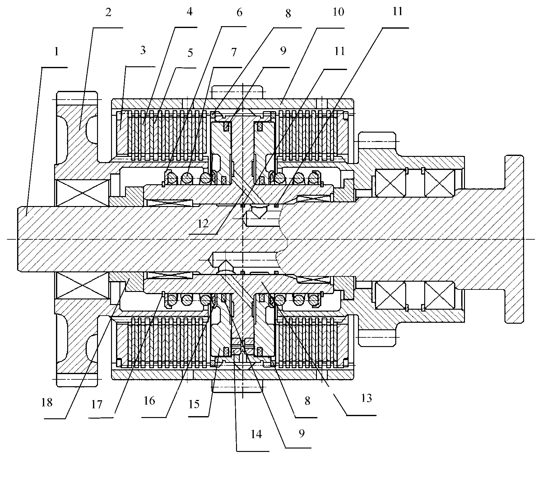
[0011] The present invention will be described in detail below in conjunction with the accompanying drawings.

[0012] see figure 1 , the present invention includes a main shaft 1, a gear 2, a hydraulic system, a power transmission system, a return system and a housing 10, the main shaft 1 is fixed on the gearbox case, and the gear 2 is positioned on the main shaft 1 through a wear pad 18 Above, one end of the power transmission system is connected to the gear 2, the other end is connected to the housing 10, and at the same time, it is connected to the hydraulic system through the return system. The hydraulic system includes a piston 15, a piston seat 13 and an oil drain valve 14. The piston 15 is fixed on the piston seat 13 through a snap ring A8, and the seal between the piston 15 and the piston seat 13 is sealed by a sealing ring A9. The oil drain valve 14 is arranged at one end of the piston seat 13 . The piston seat 13 is fixed on the housing 10 through a snap ring A8, ...


PUM


Abstract

The invention relates to an integrated structure clutch applied to a gearbox of a wheel type engineering machinery transmission system. The clutch comprises a main shaft, a gear, a hydraulic system, a power transmission system, a returning system and a casing, wherein the main shaft is fixed on a box body of the gearbox, the gear is positioned on the main shaft through an abrasion bearing pad, one end of the power transmission system is connected with the gear, the other end of the power transmission system is connected with the casing and connected with the hydraulic system through the return system simultaneously, the hydraulic system comprises a piston, a piston seat and an oil relief valve, the piston is fixed on the piston seat through a snapping ring A, the piston and the piston seat are sealed through a seal ring A, the oil relief valve is arranged at one end of the piston seat, the piston seat is fixed on the casing through the snapping ring A, the piston, the piston seat, the oil relief valve and the seal ring A form a closed oil chamber, and an oil way is arranged between the gearbox matched with the clutch and the closed oil chamber. By means of the integrated structure clutch, gear shift impact is reduced, transmission efficiency is improved, transmission accuracy of a gear pair is improved, and noises of the gearbox are reduced.

Description

technical field [0001] The invention belongs to the technical field of engineering machinery, and in particular relates to an integrated structure clutch applied to a gearbox of a transmission system of a wheeled engineering machinery with a high degree of automation. Background technique [0002] Multi-disc wet clutches are widely used in power shift gearboxes of construction machinery transmission systems. At present, in most fixed-shaft power shift gearboxes in China, multi-disc wet clutches are mostly integrated with the clutch shaft and the clutch housing. structure, this one-piece clutch structure leads to the gearbox case can only be split, the clutch shaft and the case hole must be connected through bearings, because the clutch shaft and the clutch housing are integrated, so when the clutch is working The clutch shaft will rotate together with the clutch housing, resulting in a decrease in transmission efficiency of the gearbox, greater shifting impact, and affecting...

Claims


Application Information

Patent Timeline
Patent Type & Authority Applications(China)
IPC IPC(8): F16D25/0638F16D25/12F16H57/00
Inventor 李军朱本超梁建东吴亚伟严颖波赵青陈振张赛赛智伟苏东华
Owner SHANTUI CONSTR MASCH CO LTD
Why Eureka
Try Eureka