a burner

A burner and combustion device technology, applied in the direction of burners, burners, gas fuel burners, etc., can solve the problems of incomplete combustion, poor combustion effect, high carbon monoxide concentration, etc., achieve sufficient mixing, reduce emission rate, and improve combustion efficiency effect

Active Publication Date: 2015-09-09
MEGA ENERGY SCI TECH
View PDF10 Cites 0 Cited by
  • Summary
  • Abstract
  • Description
  • Claims
  • Application Information

AI Technical Summary

Problems solved by technology

[0002] Due to insufficient mixing of gas and air, existing burners often lead to problems such as incomplete combustion, excessive heat loss, poor combustion effect, and high carbon monoxide concentration, and the firepower of existing burners is relatively concentrated at the burner head, resulting in poor heating effect

Method used


Image

  • a burner
  • a burner
  • a burner

Examples


Embodiment Construction

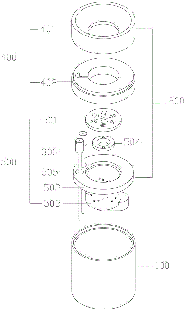
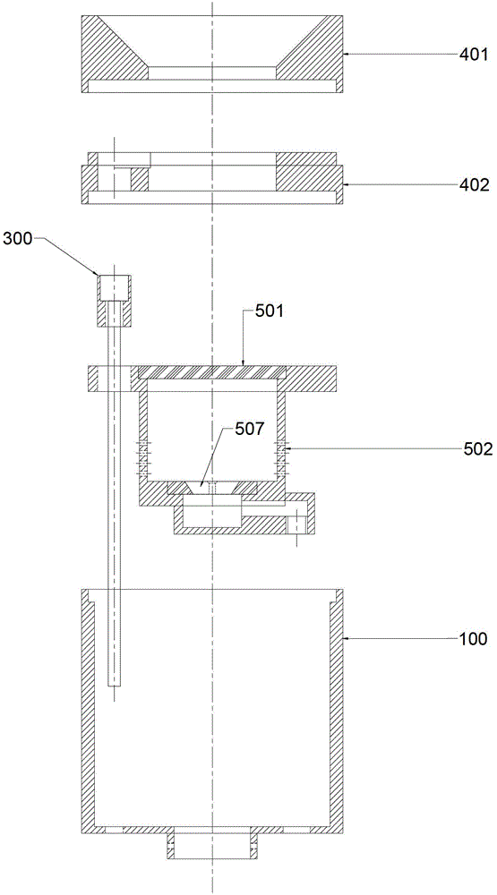
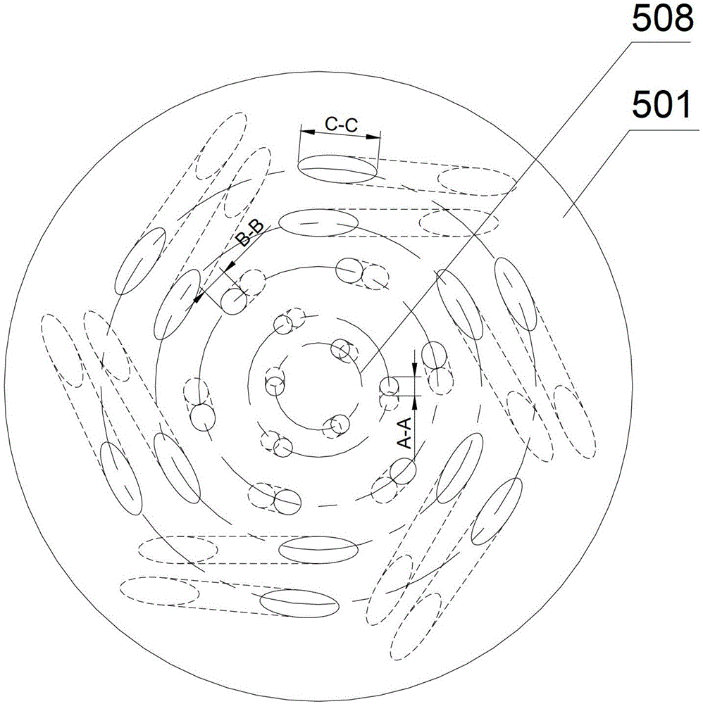
[0024] like Figure 1-2 As shown, in a preferred embodiment of the present invention, the burner includes a casing 100, and a furnace body 200 disposed in the casing, the furnace body 200 further includes an igniter 300, a combustion device 400 and an air-gas mixing device 500, air and gas The gas is mixed in the air-gas mixing device 500 , the mixed gas enters the combustion device 400 , and then is ignited by the igniter 300 to burn the mixed gas. In the present invention, a flame-stabilizing pad 501 for controlling the release of the mixture of air and gas is also provided between the combustion device 400 and the air-gas mixing device 500 . like image 3 As shown, the flame-stabilizing pad 501 is provided with multiple sets of air-gas passages 508 surrounding the center of the flame-stabilizing pad 501 (only one set of air-gas passages are marked in the figure), for the sake of distinction, in image 3 Each group of air and gas passages is marked with dotted lines, and e...


PUM


Abstract

The invention relates to a combustor. The combustor comprises a shell and a furnace body arranged in the shell, the furnace body comprises an igniter, a combustion device and an air and gas mixing device, a flame stabilizing pad used for controlling air and gas mixed gas is further arranged between the combustion device and the air and gas mixing device and is provided with a plurality of groups of air and gas passages arranged surrounding the center of the flame stabilizing pad, each group of air and gas passages comprises a plurality of holes with the axes inclining towards a certain direction, and the holes of the air and gas passages are the same in inclining direction. The flame stabilizing pad can enable the air and gas mixed gas to form spiral gas flow, so that air and gas are mixed more sufficiently, combustion efficiency of the mixed gas is improved, and emission ratio of waste gases such as carbon monoxide is further decreased.

Description

technical field [0001] The invention relates to a stove and a gas burner used in a canteen or kitchen, more specifically, to a burner. Background technique [0002] Due to insufficient mixing of gas and air, existing burners often lead to problems such as incomplete combustion, excessive heat loss, poor combustion effect, and high carbon monoxide concentration, and the firepower of existing burners is relatively concentrated at the burner head, resulting in poor heating effect . Contents of the invention [0003] The technical problem to be solved by the present invention is to provide a burner with high efficiency, energy saving, stable flame, low exhaust gas emission and low noise in view of the above defects of the prior art. [0004] The technical solution adopted by the present invention to solve the technical problem is to construct a burner, which includes an outer casing and a furnace body arranged in the outer casing, the furnace body includes an igniter, a combu...

Claims


Application Information

Patent Timeline
Patent Type & Authority Patents(China)
IPC IPC(8): F23D14/02F23D14/46F23D14/62
CPCF23D14/02F23D14/46F23D14/62F23D2209/20
Inventor 姚康明
Owner MEGA ENERGY SCI TECH
Why Eureka
Try Eureka