System and method for optical gauge sample stage calibration

A technology for optical measurement and sample stage, which is applied in the field of optical path system calibration of precision optical measurement instruments to achieve high-precision calibration and wide application prospects.

Active Publication Date: 2015-05-06
HUAZHONG UNIV OF SCI & TECH
View PDF12 Cites 0 Cited by
  • Summary
  • Abstract
  • Description
  • Claims
  • Application Information

AI Technical Summary

Problems solved by technology

This method is highly reproducible for individual sample pitch adjustments

Method used


Image

  • System and method for optical gauge sample stage calibration
  • System and method for optical gauge sample stage calibration
  • System and method for optical gauge sample stage calibration

Examples


Embodiment Construction

[0030] The principle and working process of the method of the present invention will be described in further detail below in conjunction with the accompanying drawings and examples. It should be noted here that the descriptions of these embodiments are used to help understand the present invention, but are not intended to limit the present invention. In addition, the technical features involved in the various embodiments of the present invention described below can be combined with each other as long as they do not constitute a conflict with each other.

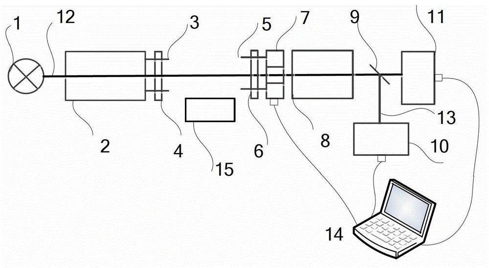
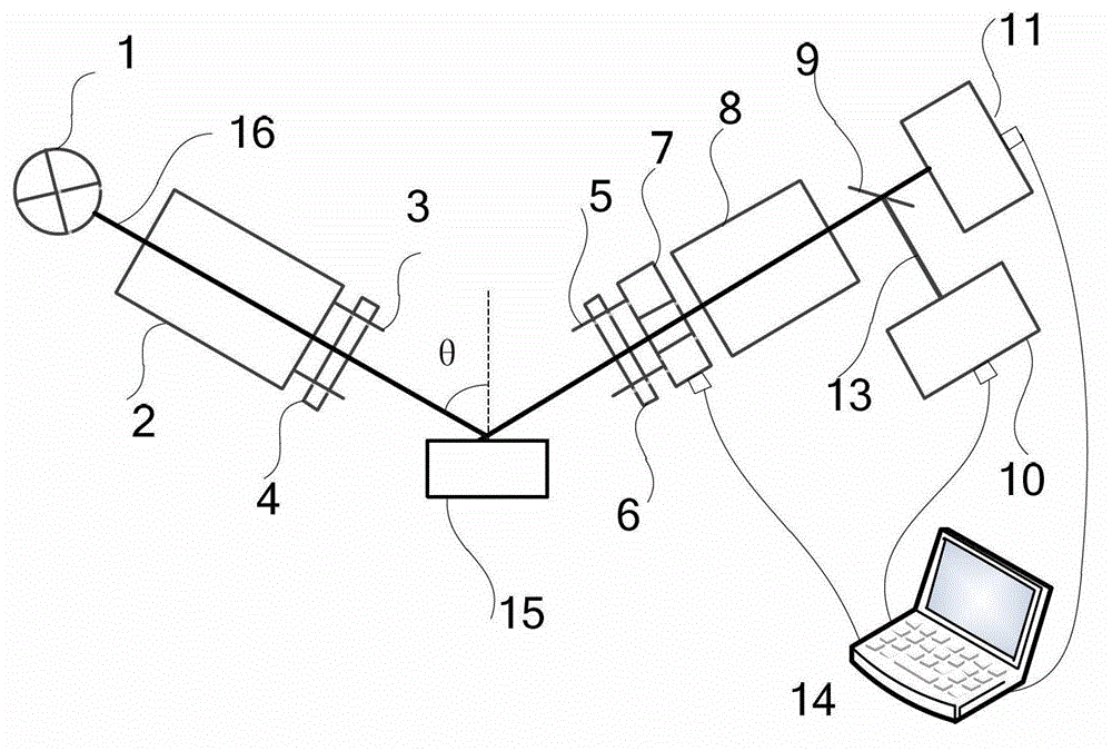
[0031] like figure 1 As shown, it is a system for calibrating the sample stage of an optical measuring instrument provided by the present invention. The system includes a light source 1, a polarizer arm 2, a front four-quadrant detector 7, an analyzer arm 8, a beam splitter 9, and a built-in Four-quadrant detector 10, CCD detector 11 and computer 14.

[0032] The first lens adjustment platform 4 and the first adjustment kno...


PUM


Abstract

The invention discloses a system and a method for optical gauge sample stage calibration. Alignment of an optical path system is carried out under the condition that an ellipsometer is of a straight-through type. The method for the optical gauge sample stage calibration includes calibration of a front optical path and a back optical path. Due to a knob on an oblique incidence type crude regulation the sample stage of the ellipsometer, a polarization detection arm optical receiver hole can receive a part of light beams; the knob on the sample stage is finely regulated so that a cross cursor indicating the light beams can appear at the central position; and a system front portion and system back portion scan in the Z-axis direction with a step length 1, overall light intensity received by a detector at each height position is recorded, a light intensity curve is drawn, and the system automatically selects the position where the maximum light intensity value is located as the optimal relative height position of the sample stage. The system for the optical gauge sample stage calibration mainly comprises a light source, a polarizing arm, a front-arranged four-quadrant detector, a polarization detection arm, a spectroscope, an internally-arranged four-quadrant detector, a charge coupled device (CCD) detector and a computer. By means of the method for the optical gauge sample stage calibration, inclination angles and heights of the sample stage can be calibrated with high precision, besides, response is fast, and operation is simple.

Description

technical field [0001] The invention belongs to the field of optical path system calibration of precision optical measuring instruments, and in particular relates to a system and method for calibrating the sample stage of optical measuring instruments, which is suitable for adjusting the inclination angle and the inclination angle of the sample stages of ellipsometers and other similar optical measuring instruments. Altitude is precisely calibrated. Background technique [0002] A spectroscopic ellipsometer is an optical measurement device used to detect the thickness of a sample film, optical constants, and the microstructure of a material. Place the sample on the sample stage of the ellipsometer or similar system, project a beam of polarized light on the sample at an oblique incident angle, and the beam enters the detector after being reflected by the sample. In order to obtain accurate measurement results, some parameters that can be adjusted in the experiment (including...

Claims


Application Information

Patent Timeline
Patent Type & Authority Patents(China)
IPC IPC(8): G01M11/02
Inventor 刘世元李苏斌陈修国李伟奇张传维
Owner HUAZHONG UNIV OF SCI & TECH
Why Eureka
Try Eureka