Generation method and device of CKE signal

A technology of clock signal and generation method, which is applied in the field of communication, can solve the problems of difficulty in layout and wiring of staff, large number of clock enabling and driving circuits, etc.

Active Publication Date: 2013-04-24
HUAWEI TECH CO LTD
View PDF4 Cites 2 Cited by
  • Summary
  • Abstract
  • Description
  • Claims
  • Application Information

AI Technical Summary

Problems solved by technology

[0005] Multiple Masters are driven by the same clock enable signal, resulting in a huge number of clock enable drive circuits
Moreover, due to the small size of the ASIC, multiple Masters are driven by the same clock enable signal, which will bring great difficulties to the layout and wiring of the staff.

Method used


Image

  • Generation method and device of CKE signal
  • Generation method and device of CKE signal
  • Generation method and device of CKE signal

Examples


Embodiment 1

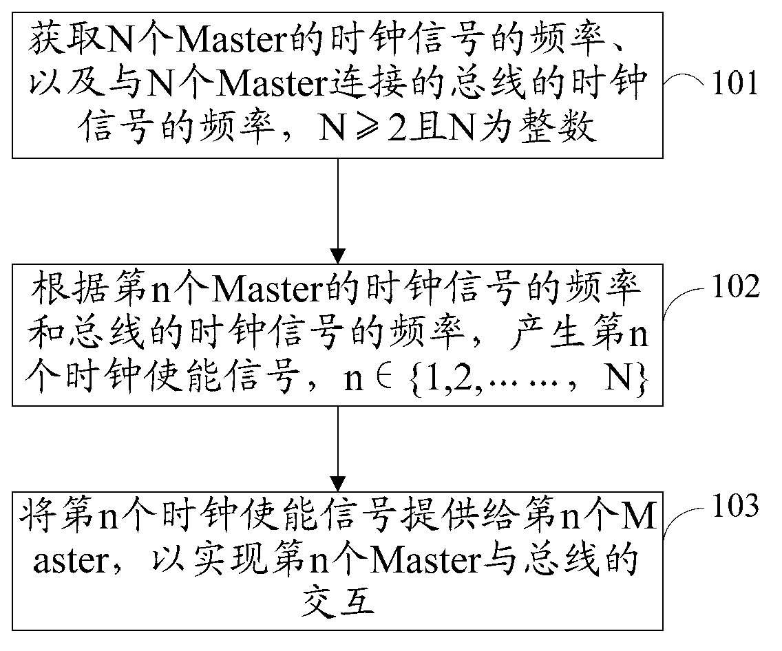
[0051] An embodiment of the present invention provides a method for generating a clock enable signal, see figure 1 , the method includes:

[0052] Step 101: Obtain the frequencies of clock signals of N Masters and the frequencies of clock signals of buses connected to the N Masters, where N≥2 and N is an integer.

[0053] Wherein, the Master and the bus adopt a synchronous architecture, and it is easy to know that in the synchronous architecture, the clock signal of the Master and the clock signal of the bus are both generated by frequency division of the same source clock.

[0054] Further, since the clock signal of the Master and the clock signal of the bus are both generated by frequency division of the same source clock, the frequency of the clock signal of the Master and the frequency of the clock signal of the bus can be represented by their frequency division coefficient relative to the source clock, Such as 2 frequency division, 3 frequency division and so on.

[005...

Embodiment 2

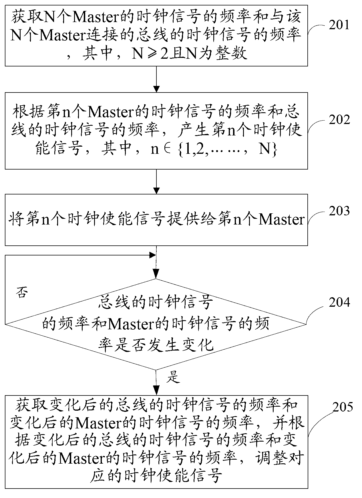
[0067] An embodiment of the present invention provides a method for generating a clock enable signal, see figure 2 , the method includes:

[0068] Step 201: Obtain the frequencies of clock signals of N Masters and the frequencies of clock signals of buses connected to the N Masters, where N≥2 and N is an integer.

[0069] Among them, the N masters and the bus adopt a synchronous architecture. It is easy to know that in the synchronous architecture, the frequency of the clock signal of the bus and the frequency of the clock signal of the Master are generated based on the same source clock, usually in the same frequency or multiplied relationship. Therefore, the frequency of the clock signal of the master and the frequency of the clock signal of the bus can be represented by their frequency division coefficient relative to the source clock, such as frequency division by 2, frequency division by 3, and so on.

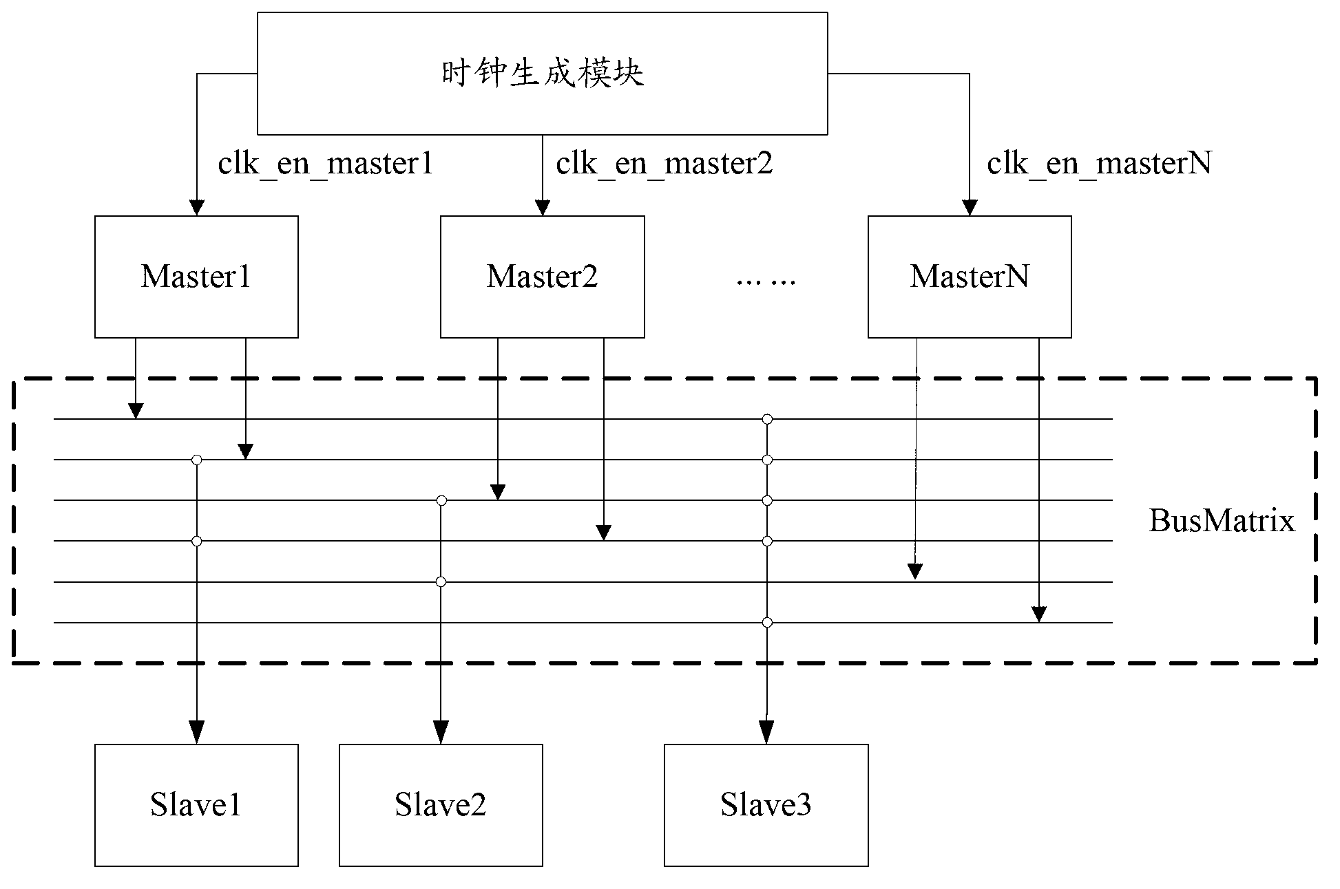
[0070] Specifically, see image 3 , in the synchronization archit...

Embodiment 3

[0091] An embodiment of the present invention provides a method for generating a clock enable signal, see Figure 5 , the method includes:

[0092] Step 301: Obtain the frequencies of clock signals of N Masters and the frequencies of clock signals of buses connected to the N Masters, where N≥2 and N is an integer.

[0093] This step 301 is the same as step 201 in Embodiment 2 of the present invention, and will not be described in detail here.

[0094] Step 302: Generate the nth preliminary clock enable signal based on the source clock according to the frequency of the clock signal of the nth Master and the frequency of the clock signal of the bus, where n∈{1,2,...,N}.

[0095] Wherein, the high level duration of the nth preparation clock enable signal is one clock cycle of the nth Master; and the falling edge of the nth preparation clock enable signal is higher than the rising edge of the clock signal of the corresponding bus Edge, one clock cycle ahead of the nth Master.

...


PUM


Abstract

The utility model discloses a generation method and a device of CKE signals and belongs to the field of communication. The generation method includes: obtaining frequencies of the clock signals of N Masters and frequencies of the clock signals of buses which are connected with the N Masters, the clock signals of the N Masters and the clock signals of the buses are generated based on the same source clock, N is not less than 2 and N is an integer, the nth CKE signal is produced according to the frequency of the nth clock signal of the Master and the frequency of the clock signal of the buses, n belongs to the range of 1, 2, ...N; The nth CKE signal is provided to the nth Master. The generation device of CKE signals comprises obtaining modules, generation modules and providing modules. Because every Master can individually provide a CKE signal, the generation method and the device of CKE signals has the advantages of greatly reducing the numbers of driving circuits of the CKE and being easy for operators to make placement and routing.

Description

technical field [0001] The invention relates to the communication field, in particular to a method and device for generating a clock enable signal. Background technique [0002] In ASIC (Application Specific Integrated Circuits, Application Specific Integrated Circuits), often multiple Masters (also known as Cores) (master devices) access multiple Slaves (slave devices) through the bus interconnection structure. ASICs include both synchronous and asynchronous architectural approaches. In the synchronous architecture mode, the clock signals of Master, Slave and the bus are generated from the same source clock using frequency division logic, and the clock frequencies of each clock signal are in the same frequency or multiplied relationship. [0003] Wherein, the Master samples the data of the bus at the rising edge of the clock signal of the Master, so as to realize the data and instruction interaction between the Master and the bus. The bus transmits valid data at the high ...

Claims


Application Information

Patent Timeline
Patent Type & Authority Applications(China)
IPC IPC(8): G06F1/06
Inventor 相海英廖水清
Owner HUAWEI TECH CO LTD
Why Eureka
Try Eureka