Temperature regulating system

a technology of temperature regulation system and temperature regulation system, which is applied in the direction of engine lubrication, gear lubrication/cooling, engine cooling apparatus, etc., can solve the problems of rapid heating up of hydraulic oil and the inability of hydraulic oil to function effectively as a working fluid, so as to reduce the power loss of components rotating in the oil bath and increase the heat. rapid

Inactive Publication Date: 2005-05-31
VOLVO CONSTR EQUIP COMPONENTS AB
View PDF3 Cites 41 Cited by
  • Summary
  • Abstract
  • Description
  • Claims
  • Application Information

AI Technical Summary

Benefits of technology

[0012]An objective of the invention is to produce a temperature regulating system for a vehicle, which affords opportunities for more effective operation of the vehicle with regard to energy efficiency. Another objective is to bring about reduced wear of components of the vehicle intended for rotation, which are cooled and / or lubricated. A further objective is that the temperature regulating system should afford opportunities for more cost-effective manufacture of the vehicle. The temperature regulating system is moreover intended to afford opportunities for simple and time-efficient maintenance.
[0017]As the gearbox and the axles are provided with oil from the same tank, a smaller quantity of hydraulic oil is required overall. Furthermore, opportunities are afforded for a more space-efficient hydraulic arrangement. Because of the smaller required quantity of hydraulic oil, the invention is also advantageous from an environmental point of view. Still further, because use is made of only one container, the hydraulic oil is topped up / changed in only one place, which is time-efficient.
[0018]According to one embodiment of the invention, at least one space previously used for housing one of the components is adapted for a dry sump. In this way, power losses related to the fact that components rotate in an oil bath can be reduced. These losses are usually referred to as drag losses.
[0021]According to another embodiment of the invention, the reservoir container is located apart from the lubricated rotating components forming part of the axle and from the rotating components forming part of the gearbox. In this way, power losses related to the fact that components rotate in an oil bath can be reduced. Again, these losses are usually referred to as drag losses.
[0022]According to another inventive embodiment, the temperature regulating system comprises an arrangement for regulating the temperature of the oil in the hydraulic arrangement via a heat exchanger unit. This temperature regulating arrangement is also adapted to cool the engine of the vehicle. One advantage of this arrangement is realized when cold starts take place. During start-up of the vehicle, the engine is started with the gearbox in neutral. This results in the engine heating up more rapidly than the gearbox. Because of the provided heat exchanger unit, heat is transferred from the coolant of the engine to the hydraulic oil and in this way the oil is heated-up more rapidly.

Problems solved by technology

The charge air cooler cools the charge air as soon as the internal combustion engine is started, which results in rapid heating up of the hydraulic oil via the first heat exchanger.
During operation of the shovel, the hydraulic oil may become too hot to function effectively as a working fluid.

Method used


Image

  • Temperature regulating system
  • Temperature regulating system
  • Temperature regulating system

Examples


Embodiment Construction

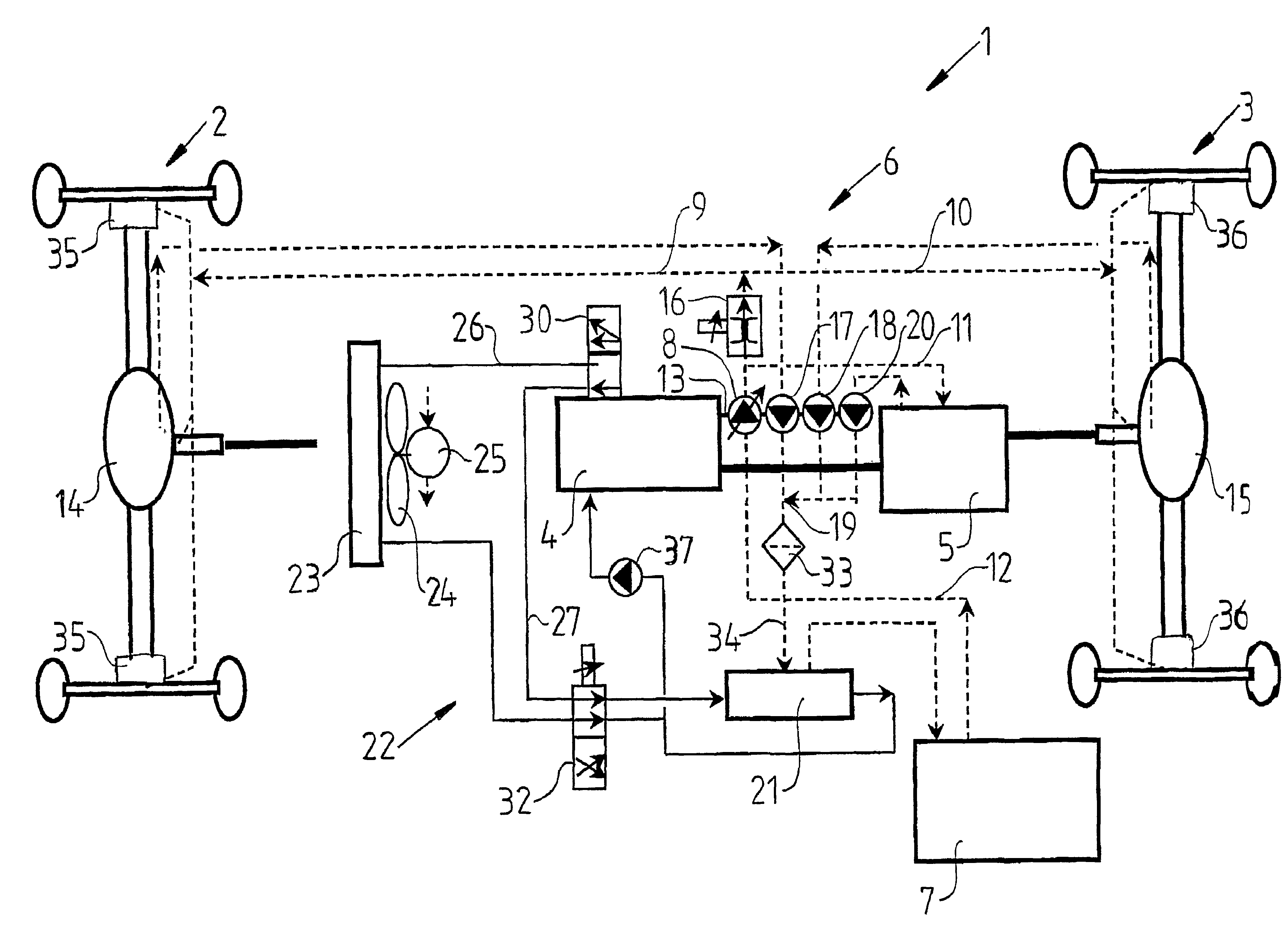
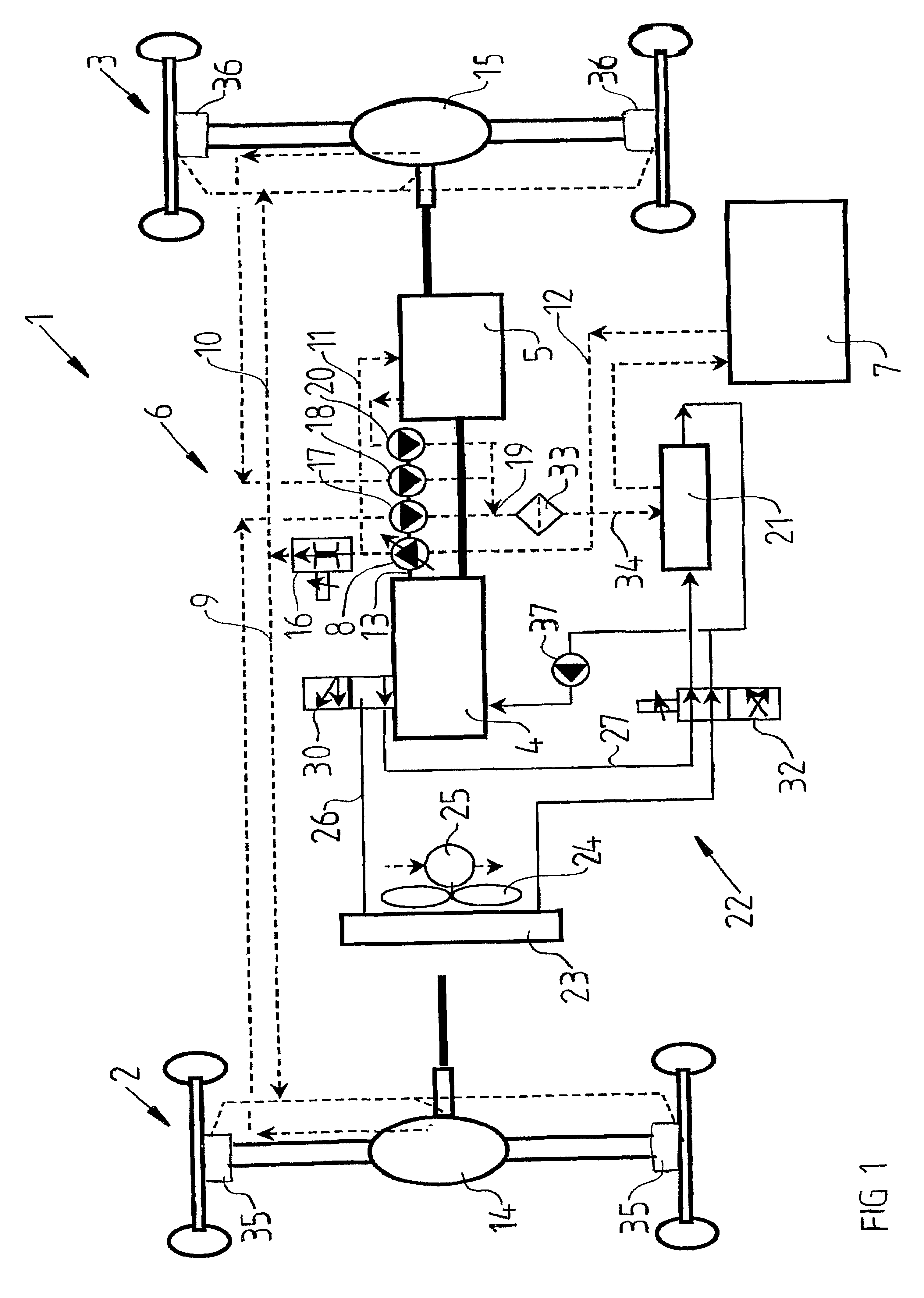
[0026]FIG. 1 shows an hydraulic oil and coolant diagram for a temperature regulating system 1 for a vehicle exemplarily in the form of a wheel loader. The wheel loader comprises a rear axle 2, a front axle 3, a diesel engine 4 and a gearbox 5 connected to the engine. Connected between the gearbox 5 and the front and rear axles is a transfer gearbox (not shown) for distributing the power to the rear axle and the front axle.

[0027]In this context, rear axle or front axle 2, 3 is used to refer to the whole mechanical construction that transmits driving power to driving wheels on the right and the left side of the axle. The rear axle 2 comprises a rear axle box which encloses a central gear 14, by means of which the driving power is turned through 90°. From the central gear, the driving power is transmitted via driving axles to the driving wheels. The central gear comprises a pinion, a drive gear and a differential gear. A hub reduction gear in the form of a planetary gear (not shown) is...


PUM


Abstract

Method and arrangement for providing a temperature regulating system (1) in a vehicle. The system includes an hydraulic arrangement (6) that is adapted to provide components intended for rotation belonging to a gearbox (5) of the vehicle and at least one of the axles (2, 3) of the vehicle with hydraulic oil from the same container (7). The system also has an arrangement (22) for regulating the temperature of the oil in the hydraulic arrangement (6) via a heat exchanger unit (21). The temperature regulating arrangement (22) is also adapted to cool the engine (4) of the vehicle.

Description

CROSS REFERENCE TO RELATED APPLICATIONS[0001]This present application is a continuation-in-part patent application of International Application No. PCT / SE02 / 00010 filed 4 Jan. 2002 which was published in English pursuant to Article 21(2) of the Patent Cooperation Treaty, and which claims priority to Swedish Application No. 0100386-2 filed 7 Feb. 2001. Both applications are expressly incorporated herein by reference in their entireties.BACKGROUND OF INVENTION[0002]1. Field of the Invention[0003]The present invention relates to a temperature regulating system for a vehicle. The invention will be described below for a case where the temperature regulating system is installed in a construction vehicle in the form of a wheel loader. This is a preferred, but in no way limiting, application of the invention.[0004]An example of an application of the temperature regulating system is for heating / cooling a lubricating oil for the gearbox of the vehicle. This comprises (includes, but is not lim...

Claims


Application Information

Patent Timeline
Patent Type & Authority Patents(United States)
IPC IPC(8): F16H57/04
CPCF16H57/0413F16H57/0412
Inventor CARLSSON, SVEN-AKE
Owner VOLVO CONSTR EQUIP COMPONENTS AB
Why Eureka
Try Eureka