Storage battery plate wrapping machine

A battery and wrapping machine technology, applied in the field of batteries, can solve problems such as increased workload of workers, waste of resources, and increased production costs of batteries

Inactive Publication Date: 2013-04-24
QUANZHOU BAISHENGTONG PLASTIC ELECTRONICS
View PDF7 Cites 11 Cited by
  • Summary
  • Abstract
  • Description
  • Claims
  • Application Information

AI Technical Summary

Problems solved by technology

[0003] In order to solve this defect, a battery plate wrapping machine has appeared on the market that can replace manual operation, improve production efficiency, and reduce the contact between workers and the plate. However, this battery plate wrapping machine is for each battery. The pole plates are packaged, and after each pack of battery pole plates, workers need to pack them up and stack them together, and when the battery pole plates are placed in the battery plate slots for charging, there are three battery pole plates or five battery pole plates. The plates are stacked together and placed in a plate slot for charging, but no matter whether the number of battery plates in the plate slot is three or five, the stacking method of each battery plate in the plate slot is two negative battery poles. A positive battery plate covered with glass wool is stacked between the plates, that is, the battery plates wrapped by the above-mentioned battery plate wrapping machine and stacked together are placed in the plate groove of the battery When charging, workers need to remove and discard the glass wool wrapped in the negative battery plate, which undoubtedly increases the workload of workers, and causes a waste of resources and an increase in the production cost of the battery

Method used


Image

  • Storage battery plate wrapping machine
  • Storage battery plate wrapping machine
  • Storage battery plate wrapping machine

Examples


Embodiment Construction

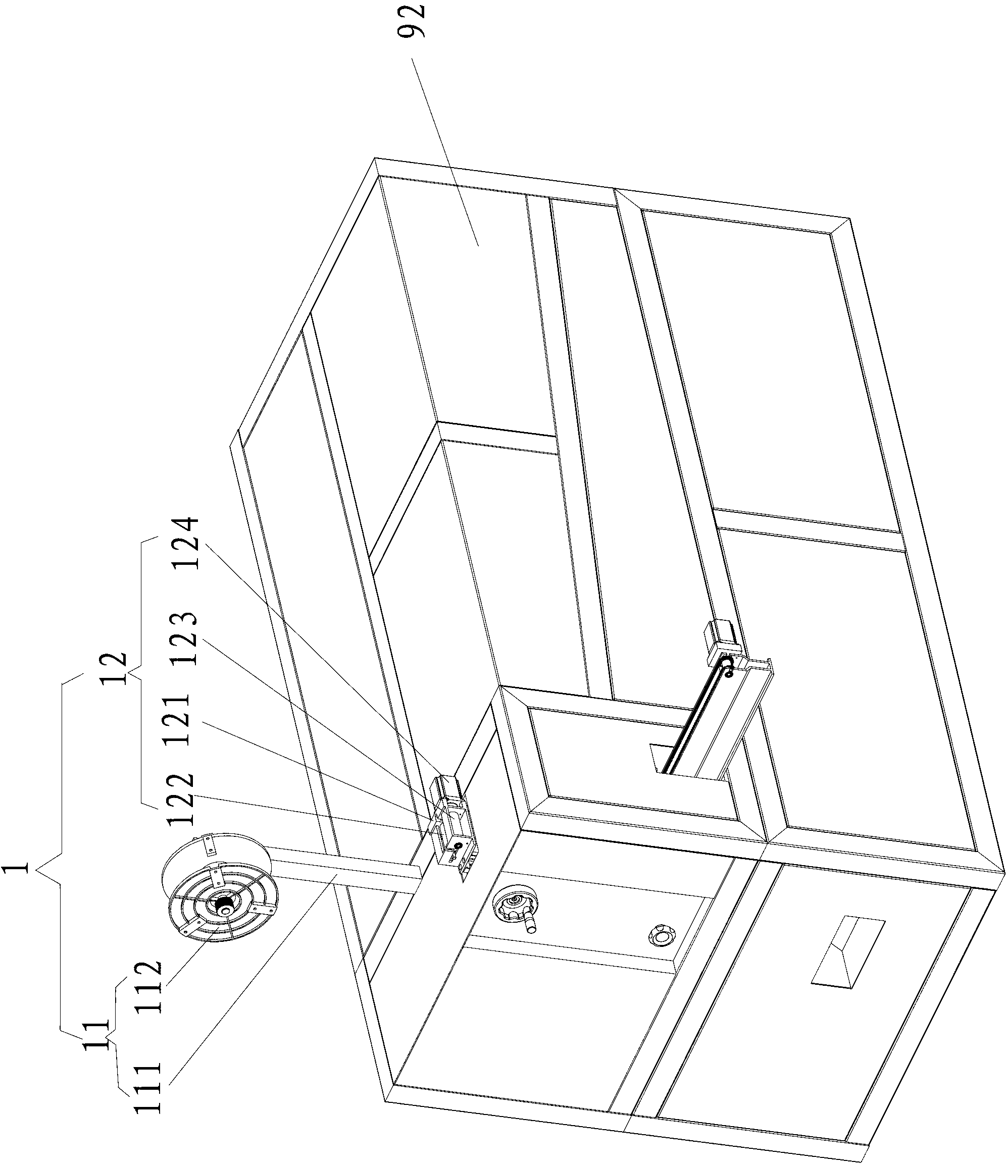
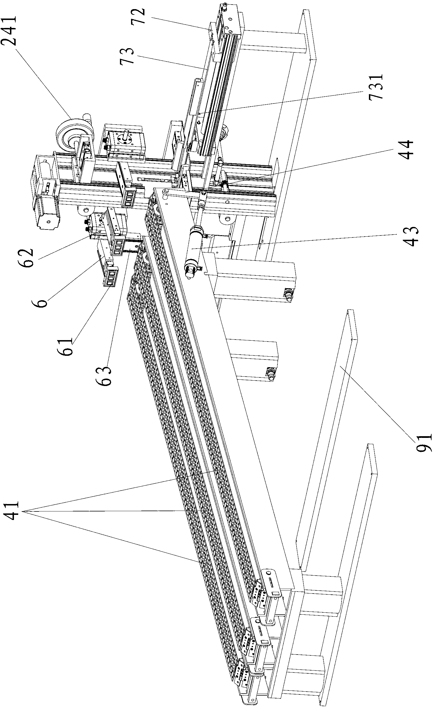
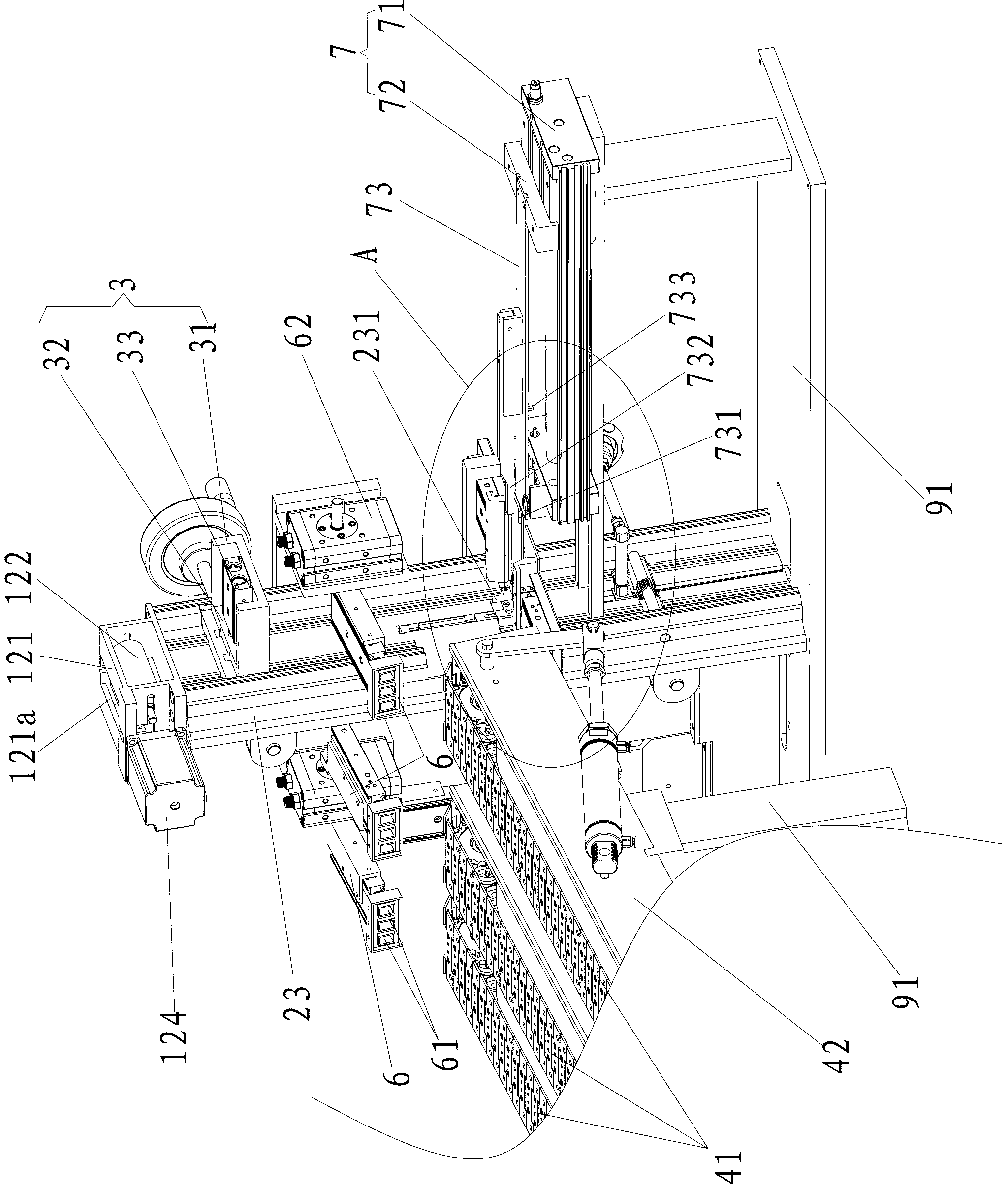
[0027] The accumulator polar plate wrapping machine of the present invention, as Figure 1-10 As shown, it includes a cotton feeding device 1 for conveying glass wool; a cotton feeding device 2 for conveying glass wool on the cotton feeding device 1 to be placed inside, and a cutting device for cutting the glass wool in the cotton feeding device 2 Cotton device 3; plate feeding device 4 for transporting battery plates; plate releasing device for placing battery plates, suction plate for sucking out battery plates on plate feeding device 4 and placing them on the plate releasing device Device 6; a plate pushing device 7 for pushing out the battery pole plate on the plate placing device; a plate ejecting device 8 for receiving and transporting the battery pole plate pushed out by the plate pushing device 7; and a frame.

[0028] The frame includes a frame body 91 and a casing 92 wrapped outside the frame body 91, the cotton feeding device 1 is arranged on the casing 91, the cott...


PUM


Abstract

The invention discloses a storage battery plate wrapping machine. The storage battery plate wrapping machine comprises a cotton delivering device for delivering glass wool, a cotton placing device for delivering the glass wool on the cotton delivering device to the cotton placing device for containing, a cotton cutting device for cutting the glass wool in the cotton placing device, a plate delivering device for delivering a storage battery plate, a plate placing device for placing the storage battery plate, a plate sucking device for sucking out the storage battery plate and arranging the storage battery plate on the plate delivering device, a plate pushing device for pushing out the storage battery plate on the plate placing device, and a plate discharging device for supporting the storage battery plate pushed by the plate pushing device and delivering the storage battery plate. Compared with the prior art, the storage battery plate on the plate discharging device is directly placed in a pole plate groove of a storage battery so as to be charged, and the cotton disassembling conducted on a negative pole storage battery plate to be wrapped after wrapping can be avoided when the storage battery plate wrapping machine is charged; and the workload of workers is greatly reduced, the glass wool can not be wasted, and the manufacturing cost of the storage battery is lowered.

Description

technical field [0001] The invention relates to the field of accumulators, in particular to an accumulator polar plate wrapping machine. Background technique [0002] At present, in the process of battery assembly and production, the wrapping process is to fold the insulating glass wool in half to form a cavity for the pole plate, and then put the battery plate into the cavity, so that the pole plate can be completed. Board wrapping process. The existing battery plate wrapping process is basically manual work, its production efficiency is low, and workers frequently contact the plate during the wrapping process, so that the lead powder and positive and negative electrode powder on the plate will stick to the workers hands, and the electrode plate contains lead powder harmful to the human body, which is not conducive to the health of the workers; at the same time, the positive and negative electrode powder stuck to the workers' hands during the wrapping process will be trans...

Claims


Application Information

Patent Timeline
Patent Type & Authority Applications(China)
IPC IPC(8): H01M10/14
CPCY02E60/126Y02E60/10Y02P70/50
Inventor 黄春萍
Owner QUANZHOU BAISHENGTONG PLASTIC ELECTRONICS
Why Eureka
Try Eureka