
Communication terminal antenna and communication system

A technology for communication terminals and communication systems, applied in the field of communication terminal antennas and communication systems, can solve the problems of less available space for antenna design, easy to be interfered, and difficult to design, so as to solve the design difficulties, reduce the interference of the antenna, and improve the performance. Effect

Inactive Publication Date: 2013-04-24
ZTE CORP
View PDF4 Cites 4 Cited by
  • Summary
  • Abstract
  • Description
  • Claims
  • Application Information

AI Technical Summary

Problems solved by technology

[0003] The main technical problem to be solved by the present invention is to provide a communication terminal antenna and a communication system to solve the problems of less available space, high cost, difficult design and easy interference faced by existing antenna designs

Method used


Image

  • Communication terminal antenna and communication system
  • Communication terminal antenna and communication system
  • Communication terminal antenna and communication system

Examples


Embodiment Construction

[0021] The present invention will be further described in detail below through specific embodiments in conjunction with the accompanying drawings.

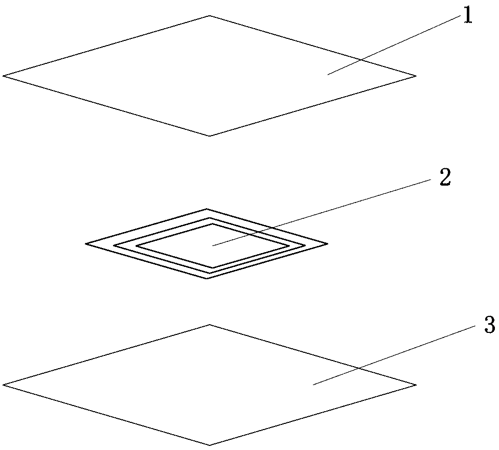
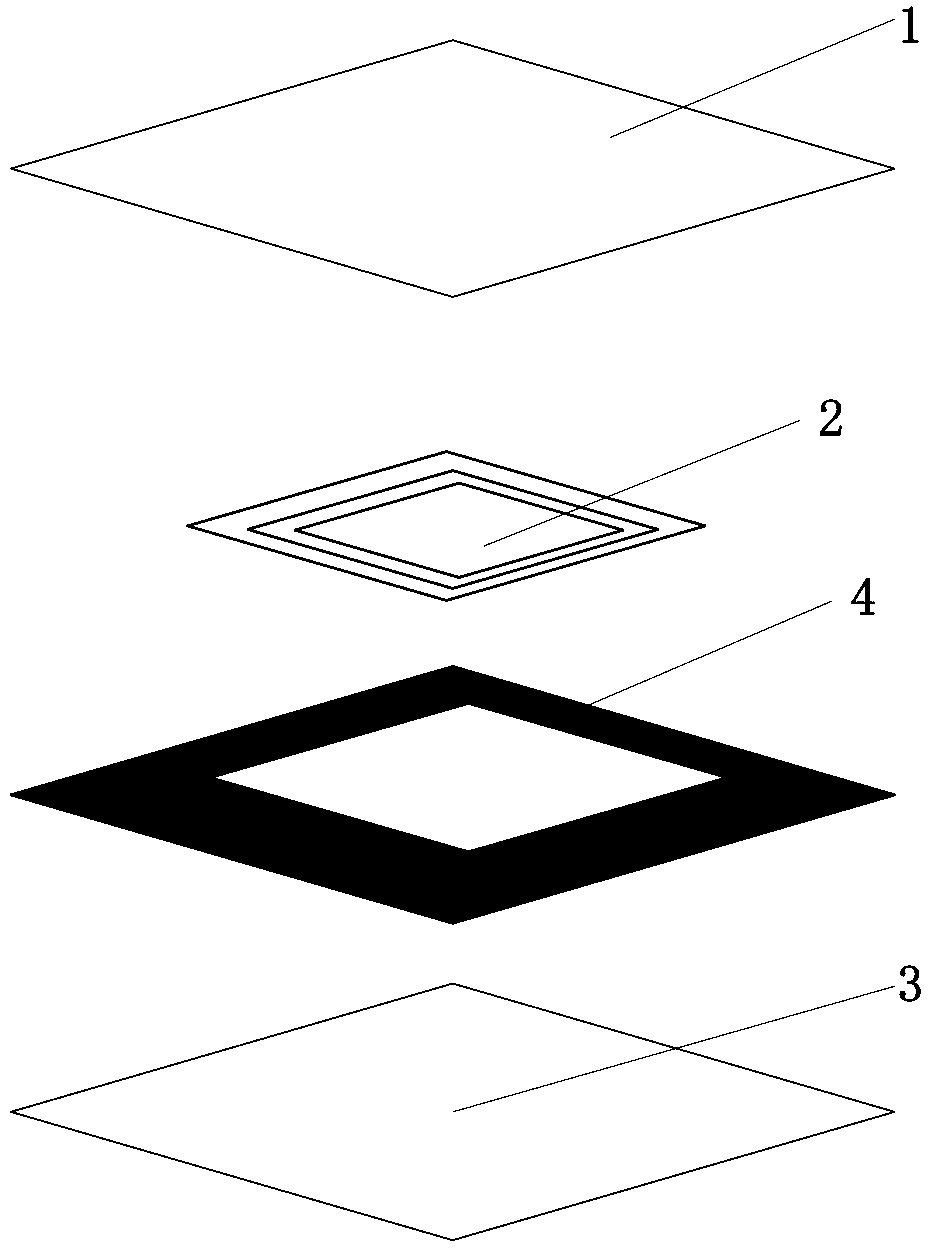
[0022] The communication terminal antenna in this embodiment is an external antenna of the communication terminal, which can be detachably connected to the communication terminal. See figure 1 As shown, the communication terminal antenna includes a first protective layer 1, a third protective layer 3 arranged in sequence from top to bottom, and an antenna body 2 arranged between the first protective layer 1 and the third protective layer 3, and also includes An antenna connecting piece (not shown in the figure) connected with the antenna main body 2, and the antenna main body 2 is effectively connected with the communication terminal through the antenna connecting piece. Specifically, the antenna connector can be effectively connected to the communication terminal through a feed contact or a feed interface provided on the termina...


PUM


Abstract

The invention discloses a communication terminal antenna and a communication system, wherein the antenna of a communication terminal is arranged outside the communication terminal and is used as an external antenna; and the antenna specifically comprises a first protection layer, a second protection layer, a third protection layer and an antenna body, and further comprises an antenna connection piece, wherein the first protection layer, the second protection layer and the third protection layer are sequentially arranged from top down, the antenna body is arranged between the first protection layer and the third protection layer, and the antenna body is connected with the communication terminal through the antenna connection piece. Therefore, the technical scheme is that the antenna is arranged on the communication terminal in an external mode, because the antenna is arranged in an external mode, the problem that usable space is not enough when the antenna is arranged inside the terminal can be solved, and design and use costs are reduced; meanwhile, when the antenna is designed to be arranged outside the communication terminal to ensure that the antenna is separated from a circuit board, a battery and the like inside the terminal, interference in the antenna can be reduced, performance of the antenna is improved, and accordingly satisfaction of user experiences is improved.

Description

technical field [0001] The invention relates to the communication field, in particular to a communication terminal antenna and a communication system. Background technique [0002] At present, as smartphones are becoming thinner and lighter, especially when the thickness is less than 7-8mm, it is a great challenge for RF and structural engineers to design GPS antennas and NFC antennas that work well in crowded structures. Antennas used in mobile phones (IFA, PIFA, monopole, etc.) need a relatively good distance or clearance from the ground. Generally speaking, the height above 6.5mm is better. The antenna layout structure of mobile phones mainly meets the needs of 3G and LTE diversity and In the case of major communication requirements such as WiFi / BT, it is difficult to have a good space structure for less used wireless modules such as GPS or NFC. GPS modules used in communication terminals have extremely high requirements for receiving sensitivity. At present, the initial...

Claims


Application Information

Patent Timeline
IPC IPC(8): H01Q1/24H01Q1/38
CPCH01Q1/242H01Q7/00H01Q1/40H01Q1/22
Inventor 黄理焕
Owner ZTE CORP
Learn More