Data synchronization method and device
A data synchronization and data technology, which is applied in the direction of synchronization devices, electrical components, wireless communications, etc., can solve problems such as the inability to meet the load balance of key resources of telecommunication equipment, and achieve the effects of high efficiency, simplified transmission process, and flexible configuration
- Summary
- Abstract
- Description
- Claims
- Application Information
AI Technical Summary
Problems solved by technology
Method used
Image


Examples
specific Embodiment 1
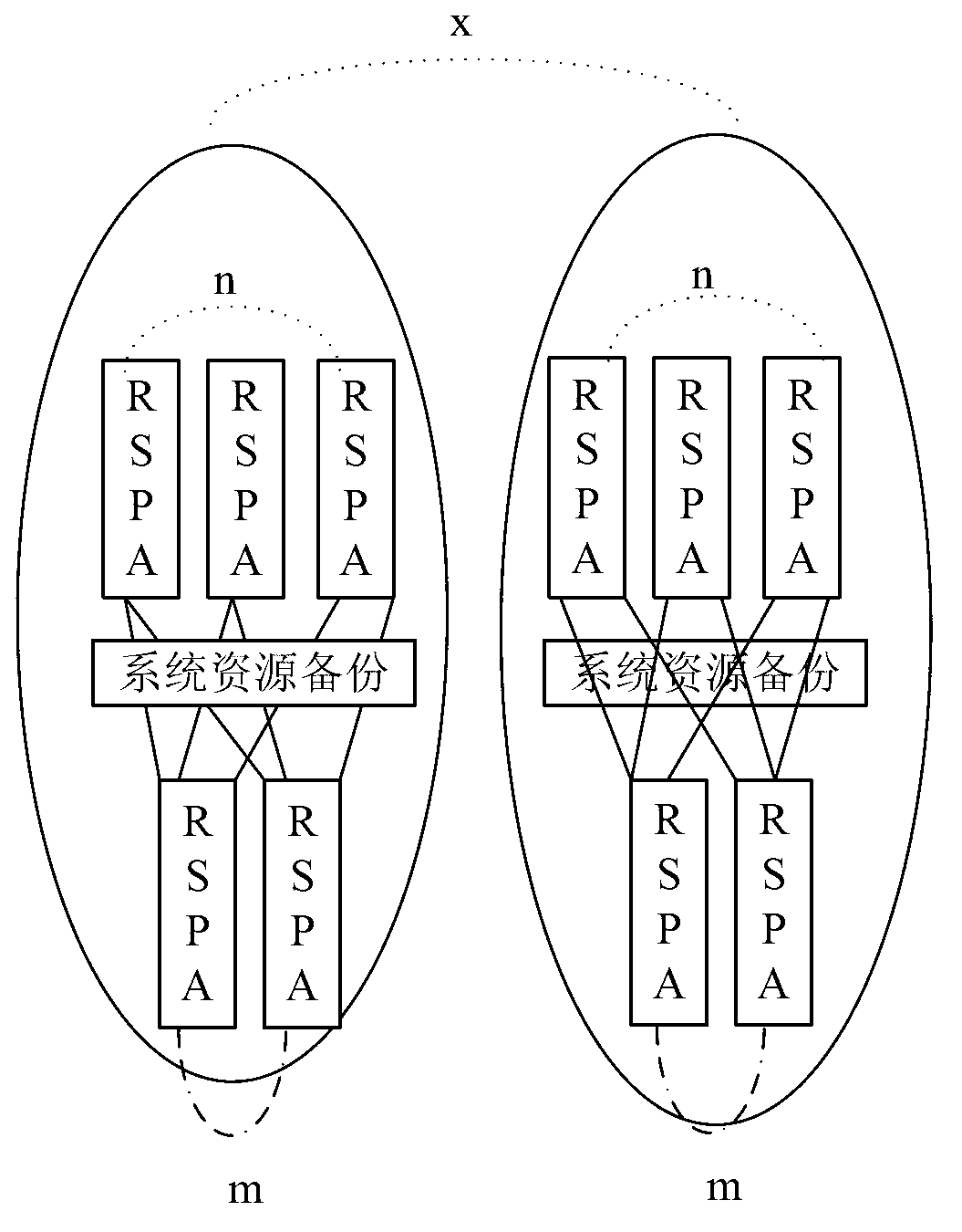
[0063] Specific embodiment 1: see Table 1 below, which is a backup relationship table provided for specific embodiments of the present invention.
[0064] In the backup relationship table, ucModule, usGroup, and ucSGroup represent the logical address of the main board in the N+M backup group, and ausBakGroup1List / aucBakSGroup1List, ausBakGroup2List / aucBakSGroup2List, ausBakGroup3List / aucBakSGroup3List represent the backup boards in the N+M backup group, respectively. That is, the logical address list of the backup board, where ausBakGroup1List / aucBakSGroup1List is the preferred backup group list. If the main board in the current backup group fails, the backup board in the backup group is preferably replaced as the main board. If all the boards in the current preferred backup group are faulty, select the normal backup boards in backup list 2 and backup list 3 in order to replace them as masters.
[0065] Table 1
[0066]
specific Embodiment 2
[0067] Specific embodiment 2: In a communication device, the data on each peripheral board needs to be consistent with the data on the central node, and data consistency between the active and standby peripheral boards must also be maintained. In order to ensure the validity and consistency of the data on each board, it is necessary to ensure the data synchronization of the database subsystem. The structure of the database subsystem is designed as a distributed processing method, and the database relationship sets are distributed on the processors of each node. The synchronization of the database subsystem specifically includes: static data synchronization and dynamic data synchronization.
[0068] Static data is the configuration data sent by the central node. When the peripheral boards are initialized and powered on, the data of the central node needs to be synchronized to each peripheral board. The static data synchronization process during the power-on process of the perip...
specific Embodiment 3
[0087] Specific embodiment 3: the logical addresses of the main board and the backup board are configured in the backup relationship table, and the logical addresses are virtual. Only by mapping the logical address to the physical address of the peripheral single board can the relationship of the single board in the backup relationship table be Corresponds to the real single board; when the system is initialized, the mapping relationship is configured by the central node. The backup relationship table and mapping relationship will be sent to all peripheral nodes.
[0088] When the active / standby switching occurs during the operation of the N+M peripheral board, it is necessary to exchange the mapping relationship between the logical address and the physical address of the active / standby board. The logical address configured as active is used, and the logical address configured as standby is used for the downgraded physical board, so as to ensure the normal communication betwee...
PUM
 Abstract
Description
Claims
Application Information
 - R&D
- Intellectual Property
- Life Sciences
- Materials
- Tech Scout
- Unparalleled Data Quality
- Higher Quality Content
- 60% Fewer Hallucinations
Browse by: Latest US Patents, China's latest patents, Technical Efficacy Thesaurus, Application Domain, Technology Topic, Popular Technical Reports.
© 2025 PatSnap. All rights reserved.Legal|Privacy policy|Modern Slavery Act Transparency Statement|Sitemap|About US| Contact US: help@patsnap.com