Butterfly radiator and optical module group and optical module group single plate with butterfly radiator

A butterfly-shaped radiator and optical module technology, which is applied in the direction of optical fiber transmission, cooling/ventilation/heating transformation, etc., can solve the problems of large changes in ambient temperature and low integration of optical fibers, so as to improve heat dissipation performance and assembly integration. Effects of Degree Requirements

Active Publication Date: 2013-04-24
GUANGXUN SCI & TECH WUHAN
View PDF4 Cites 2 Cited by
  • Summary
  • Abstract
  • Description
  • Claims
  • Application Information

AI Technical Summary

Problems solved by technology

The heat source or other devices in the optical module need to work at a certain temperature, and the ambient temperature of the optical module changes greatly. It is necessary to ensure that the operating temperature of the optical module is lower than the maximum withstand temperature, and that the optical module has a good temperature at high temperature. Heat dissipation performance; at present, due to the limitations of the existing optical module's own heat dissipation structure and the influence of the fiber output direction of the optical module, the integration of the optical module on the single board is not high.

Method used


Image

  • Butterfly radiator and optical module group and optical module group single plate with butterfly radiator
  • Butterfly radiator and optical module group and optical module group single plate with butterfly radiator
  • Butterfly radiator and optical module group and optical module group single plate with butterfly radiator

Examples


Embodiment Construction

[0026] The butterfly heat sink, the optical module group with the butterfly heat sink and the single board of the optical module group of the present invention will be described in detail below with reference to the embodiments and the accompanying drawings.

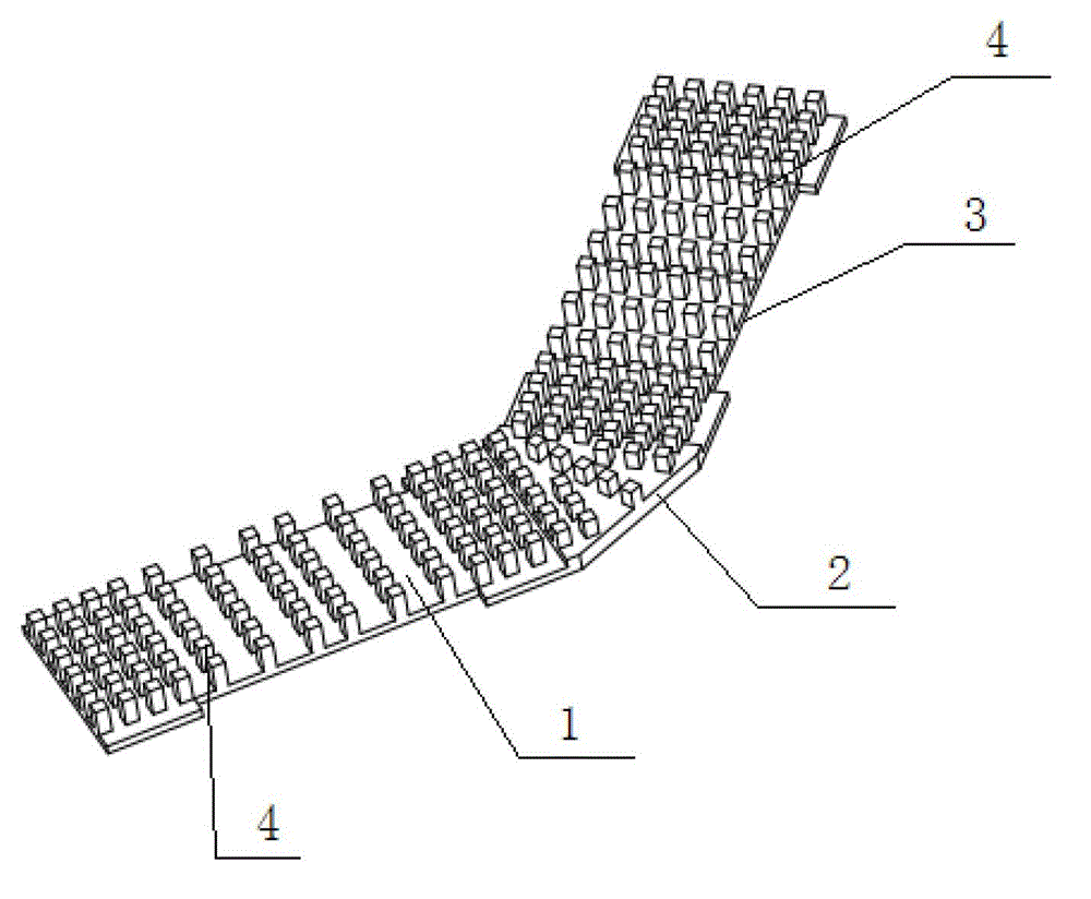
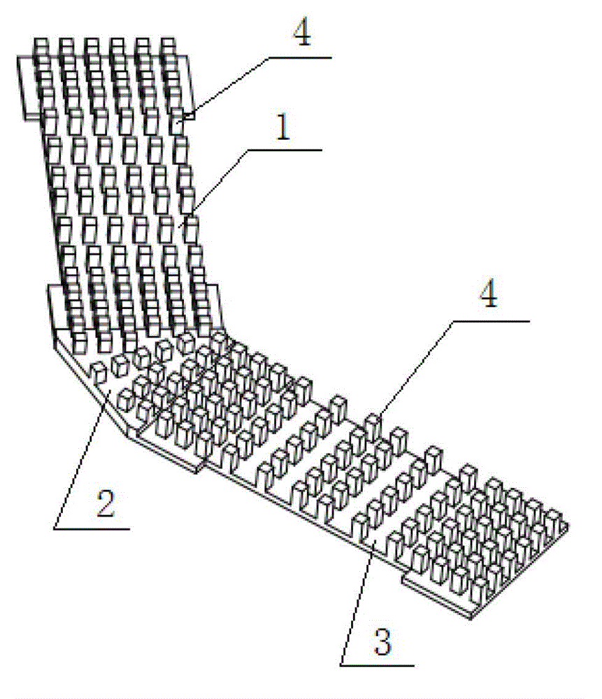
[0027] Such as figure 1 , figure 2 As shown, the butterfly radiator of the present invention includes a front bottom plate 1, the rear end of the front bottom plate 1 is integrally connected with one end of the middle bottom plate 2, and the other end of the middle bottom plate 2 is integrally connected with the back bottom plate 3. At one end, a plurality of cooling fins 4 are fixedly arranged on the front base plate 1 , the middle base plate 2 and the rear base plate 3 .

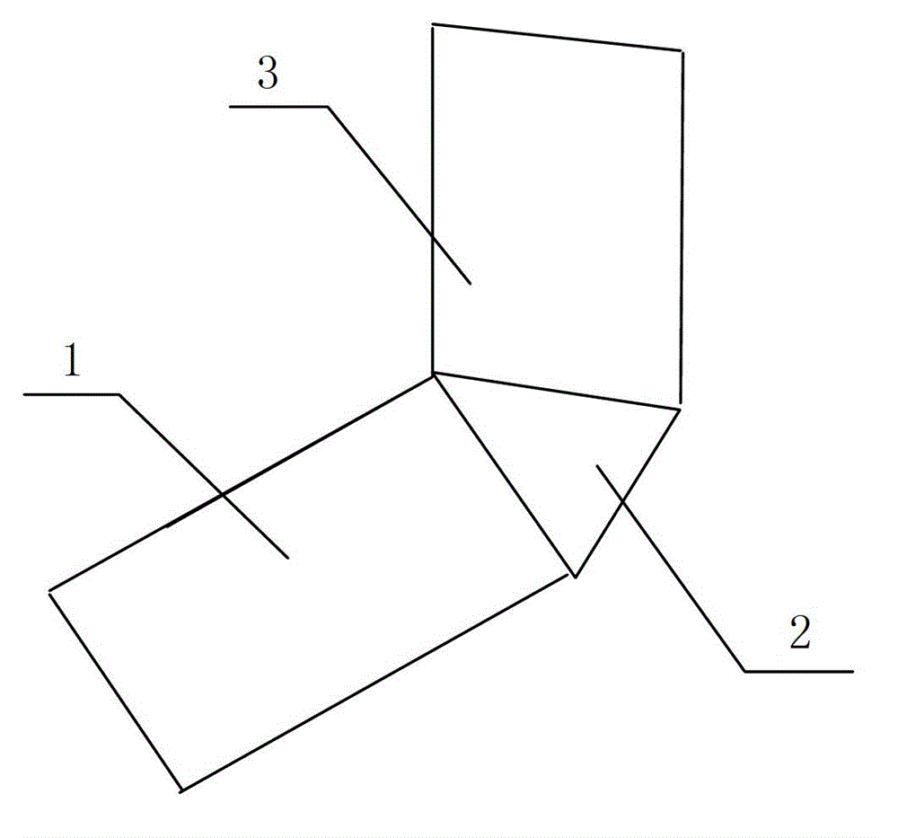
[0028] Such as image 3 As shown, the middle bottom plate 2 is an isosceles triangle structure. When the middle bottom plate 2 of the isosceles triangle structure is combined with the front bottom plate 1 and the rear bottom plate 3 by rotating 18...


PUM


Abstract

The invention provides a butterfly radiator and an optical module group and an optical module group single plate with a butterfly radiator, a middle bottom plate is arranged at the tail end of a front bottom plate of the radiator, the other end of the middle bottom plate is connected with a rear bottom plate, a plurality of cooling fins are arranged on the front bottom plate, the middle bottom plate and the rear bottom plate, the middle bottom plate is an isosceles triangle, an included angle beta formed between the two side edges on the same side of the front bottom plate and the rear bottom plate>= 2 alpha, wherein 0 degree< alpha< 90 degrees. The optical module group is provided with a base which is fixedly connected on the rear end of the optical module and a jump ring or tabletting which is arranged on the base, and a butterfly radiator is arranged on the base. The single plate is provided with a plurality of optical module groups with the same structure which complies the arranged angle alpha and abreast arranged on the circuit plate, the optical module groups are provided with the optical module arranged on a single plate panel, the base which is fixed the rear end of the optical module, the jump ring or the tabletting which is arranged the base, and the butterfly radiator which is provided with a bend is arranged on the base. The butterfly radiator and the optical module group and the optical module group single plate with a butterfly radiator have the advantages of being capable of improving level of integration and assembly of the optical module and further improving heat dissipation performance of a single optical module.

Description

technical field [0001] The invention relates to a heat dissipation structure. In particular, it relates to a butterfly radiator used in the communication field, an optical module group and a single board of the optical module group with the butterfly radiator. Background technique [0002] In the current field of communication technology, optical modules are widely used in communication equipment. The heat source or other devices in the optical module need to work at a certain temperature, and the ambient temperature of the optical module changes greatly. It is necessary to ensure that the operating temperature of the optical module is lower than the maximum withstand temperature, and that the optical module has a good temperature at high temperature. Heat dissipation performance: At present, due to the limitations of the existing optical module's own heat dissipation structure and the influence of the fiber output direction of the optical module, the integration level of t...

Claims


Application Information

Patent Timeline
Patent Type & Authority Applications(China)
IPC IPC(8): H05K7/20H04B10/25
Inventor 胡文娟伍锡杰关卫林杨明冬蒙冰王文忠喻杰奎肖光莹江毅罗勇
Owner GUANGXUN SCI & TECH WUHAN
Why Eureka
Try Eureka