

Concealed slide fastener
A technology of invisible zippers and zippers, applied in the direction of sliding fastener components, applications, fasteners, etc., can solve the problems of no record, etc., achieve the effect of improving reliability, suppressing gap leakage, and easy inventory management
- Summary
- Abstract
- Description
- Claims
- Application Information
AI Technical Summary
Problems solved by technology
Method used
Image

Examples
no. 1 approach
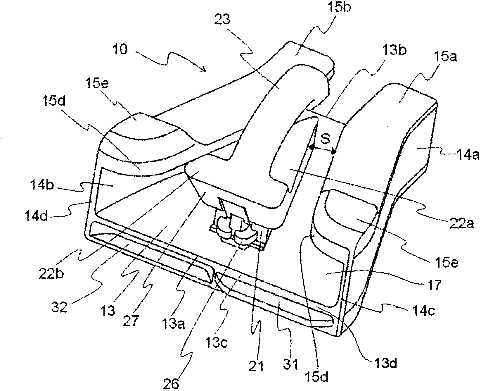
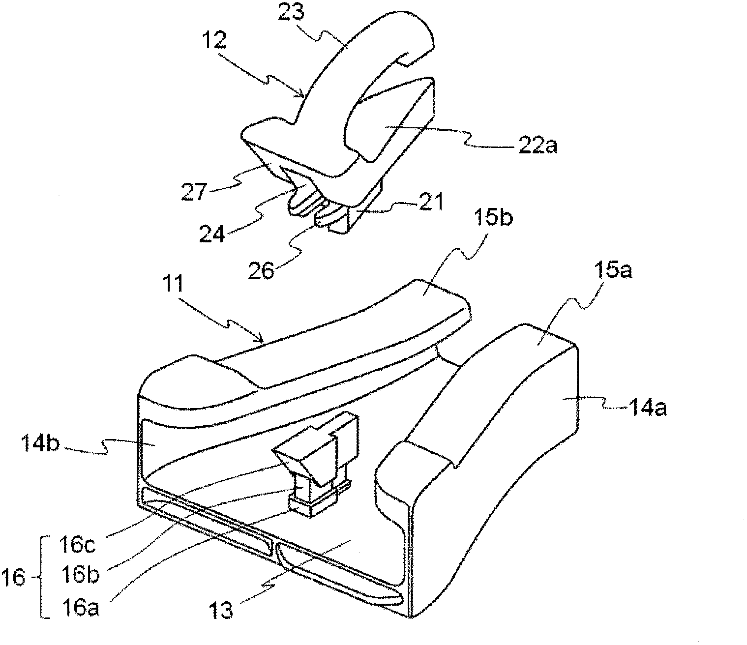
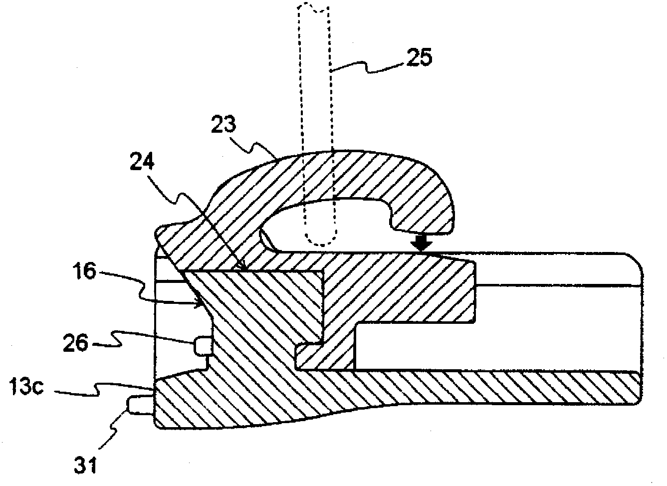
[0051] The slider 10 for electromagnetic wave shielding slide fasteners which concerns on 1st Embodiment of this invention is demonstrated. figure 1 It is a perspective view of the slider 10 of this embodiment. refer to figure 1 , The slider 10 of this embodiment has as a basic structure: a lower wing plate 13; left and right side walls 14a, 14b erected along the side edges of the lower wing plate 13 in the left and right direction; The left and right first flanges 15a, 15b extending from the upper end of the lower wing plate 13 in a direction approaching each other; The guide post 21 between 15b; the second flange 22a that is provided on the upper surface of the guide post 21 and at least protrudes toward the left and right first flanges 15a, 15b and the rear opening; The cantilever-shaped pull-tab installation part 23 of the climb 25. Moreover, in this invention, the 1st flange is expressed also as an upper wing board.
[0052] The substantially Y-shaped space in plan vi...
no. 2 approach
[0074] Next, the slider 50 for electromagnetic wave shielding slide fasteners which concerns on 2nd Embodiment of this invention is demonstrated. Figure 9 It is a perspective view of the slider 50 of this embodiment. Components that are the same as those in the first embodiment are assigned the same reference numerals, and since their structures and functions have already been described, description thereof will be omitted. The same applies to the following embodiments.
[0075] The second embodiment differs from the first embodiment in the shape of the front end surface 13 c of the lower blade 13 . In the present embodiment, the front end surface 13c of the lower blade 13 is a flat surface perpendicular to the front-rear direction. In this embodiment, although there is no unevenness on the front end surface 13c, that is, the front end surface 13c is only composed of the base surface 13d, but the left and right shapes of the front end surface 13c of the lower wing plate 13 ...
no. 3 approach
[0078] Next, the slider 60 for electromagnetic wave shielding slide fasteners which concerns on 3rd Embodiment of this invention is demonstrated. Figure 10 It is a perspective view of the slider 60 of this embodiment. Also in the third embodiment, as in the first embodiment, the left and right shapes of the front end surface 13c of the lower blade 13 are in a canceling relationship, and when the heads of the two sliders 60 of the same shape are brought into contact with each other and the slide fastener In the fully closed state, the front end surfaces 13c of the lower blades 13 of the slider 60 can be in close contact with each other. However, since its specific shape is different from that of the first embodiment, it will be described below.
[0079] In this embodiment, the front end surface 13c of the lower blade 13 has two layers of locking plates 61a, 61b and receiving portions 62a, 62b on different layers. As a result, the front end surface 13c of the lower blade 13 h...
PUM
 Abstract
Description
Claims
Application Information