Vehicle drive device

A driving device and vehicle technology, applied in the direction of power device, pneumatic power device, control drive, etc., can solve the problem of response delay and so on

Active Publication Date: 2013-04-24
HONDA MOTOR CO LTD
View PDF5 Cites 7 Cited by
  • Summary
  • Abstract
  • Description
  • Claims
  • Application Information

AI Technical Summary

Problems solved by technology

[0009] However, in the power transmission mechanism 104 described in Patent Document 1, in order to transmit the power of the electric motor 103 to the rear wheels 102, it is necessary to firmly engage the hydraulic clutch 107 so as to enable power transmission to maintain a state with a large torque capacity. , so response delay...

Method used


Image

  • Vehicle drive device
  • Vehicle drive device
  • Vehicle drive device

Examples


no. 2 approach

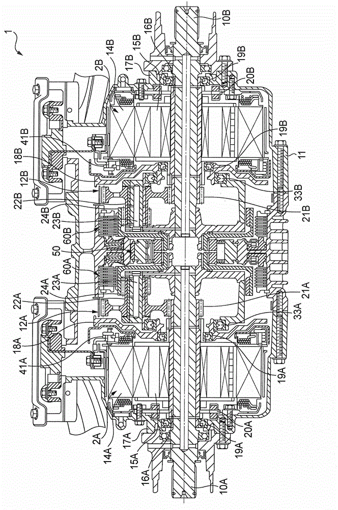
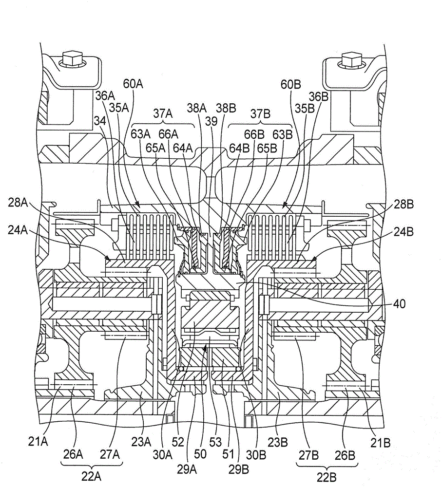
[0211] Next, refer to Figure 22 and Figure 23 , to describe the second embodiment of the present invention. It should be noted that, the drive device of the second embodiment has the same structure as the rear wheel drive device 1 of the first embodiment except for the arrangement of the hydraulic brake and the one-way clutch, so the same or equivalent parts are labeled the same or equivalent. symbols and their descriptions are omitted.

[0212] In the rear wheel drive device 1 of the present embodiment, a cylindrical space portion can be ensured between the speed reducer case 11 and the internal gear 24A, and in this space portion, the hydraulic brake 60 and the first pinion gear 26A are arranged in a radial direction. It is arranged so as to overlap upward and axially overlap with the second pinion 27A. In the hydraulic brake 60, a plurality of fixed plates 35 spline-fitted to the inner peripheral surface of the speed reducer housing 11 and a plurality of rotating plate...


PUM


Abstract

A rear-wheel drive device (1) provided with: electric motors (2A and 2B) that generate the force that drives a vehicle; hydraulic brakes (60A and 60B) that are provided on a power-transmission path between the electric motors (2A and 2B) and rear wheels (Wr), and by engaging or disengaging, connect or disconnect the motors to or from the wheels; an ECU (45) that controls the electric motors (2A and 2B) and the hydraulic brakes (60A and 60B); and a one-way clutch (50) that is provided on the power-transmission path between the electric motors (2A and 2B) and the wheels (Wr), in parallel with the hydraulic brakes (60A and 60B), and engages when forward rotation from the electric motors is inputted to the wheels, disengages when reverse rotation from the electric motors is inputted to the wheels, disengages when forward rotation from the wheels is inputted to the electric motors, and engages when reverse rotation from the wheels is inputted to the electric motors. When forward rotation from the electric motors is inputted to the wheels, the ECU (45) engages the hydraulic brakes (60A and 60B) so that the electric motors are connected to the wheels.

Description

technical field [0001] The present invention relates to a driving device for a vehicle, which includes: an electric motor generating driving force of the vehicle; and a hydraulic disconnect mechanism provided on a power transmission path between the electric motor and wheels to cut off or connect the power. Background technique [0002] The vehicle described in Patent Document 1 such as Figure 25 As shown, the front wheels are driven by a main drive source such as an engine (both not shown), and the rear wheels 102 of the vehicle 100 are driven by an electric motor 103 as an auxiliary drive source via a power transmission mechanism 104 . [0003] The power transmission mechanism 104 includes: a reduction mechanism 105 for inputting power from a motor 103 ; and a differential gear 106 for distributing the power output from the reduction mechanism 105 to the left and right rear wheels 102 , 102 . The reduction mechanism 105 is constituted by a reduction gear train, and the re...

Claims


Application Information

Patent Timeline
IPC IPC(8): F16D48/02B60K6/442B60K6/52B60K17/356B60L11/14B60L15/20B60W10/02B60W20/00B60L50/16
CPCY02T10/6217B60K2007/0092B60K6/46Y02T10/7258B60K6/52B60K17/046B60K17/356Y02T10/6265B60W10/02B60K7/0007B60K2007/0046B60W10/16B60W20/00B60W30/18127B60W20/14B60Y2400/427Y02T10/62Y02T10/72
Inventor 青木准星野谷武山本哲弘筱原势
Owner HONDA MOTOR CO LTD
Why Eureka
Try Eureka