Artificial knee-joint thighbone

A technology for artificial knee joint and femur, applied in the field of prosthesis, can solve problems such as unresolved pain, and achieve the effects of reducing the incidence, reducing the amount of osteotomy, and increasing the thickness

Active Publication Date: 2013-05-01
THYTEC SHANGHAI
View PDF6 Cites 4 Cited by
  • Summary
  • Abstract
  • Description
  • Claims
  • Application Information

AI Technical Summary

Problems solved by technology

However, this technique does not solve the problem of pain during exercise due to the small amount of osteotomy of the anterior condyle of the patient

Method used


Image

  • Artificial knee-joint thighbone
  • Artificial knee-joint thighbone
  • Artificial knee-joint thighbone

Examples


Embodiment 1

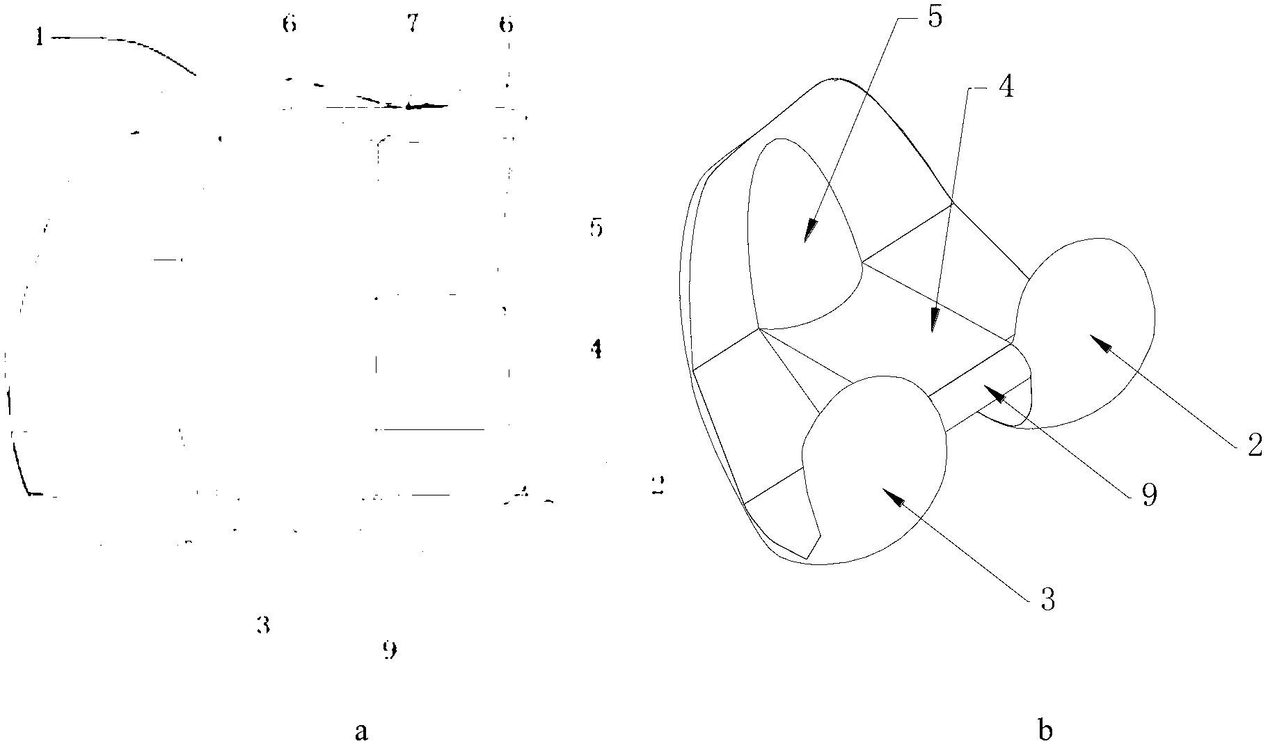
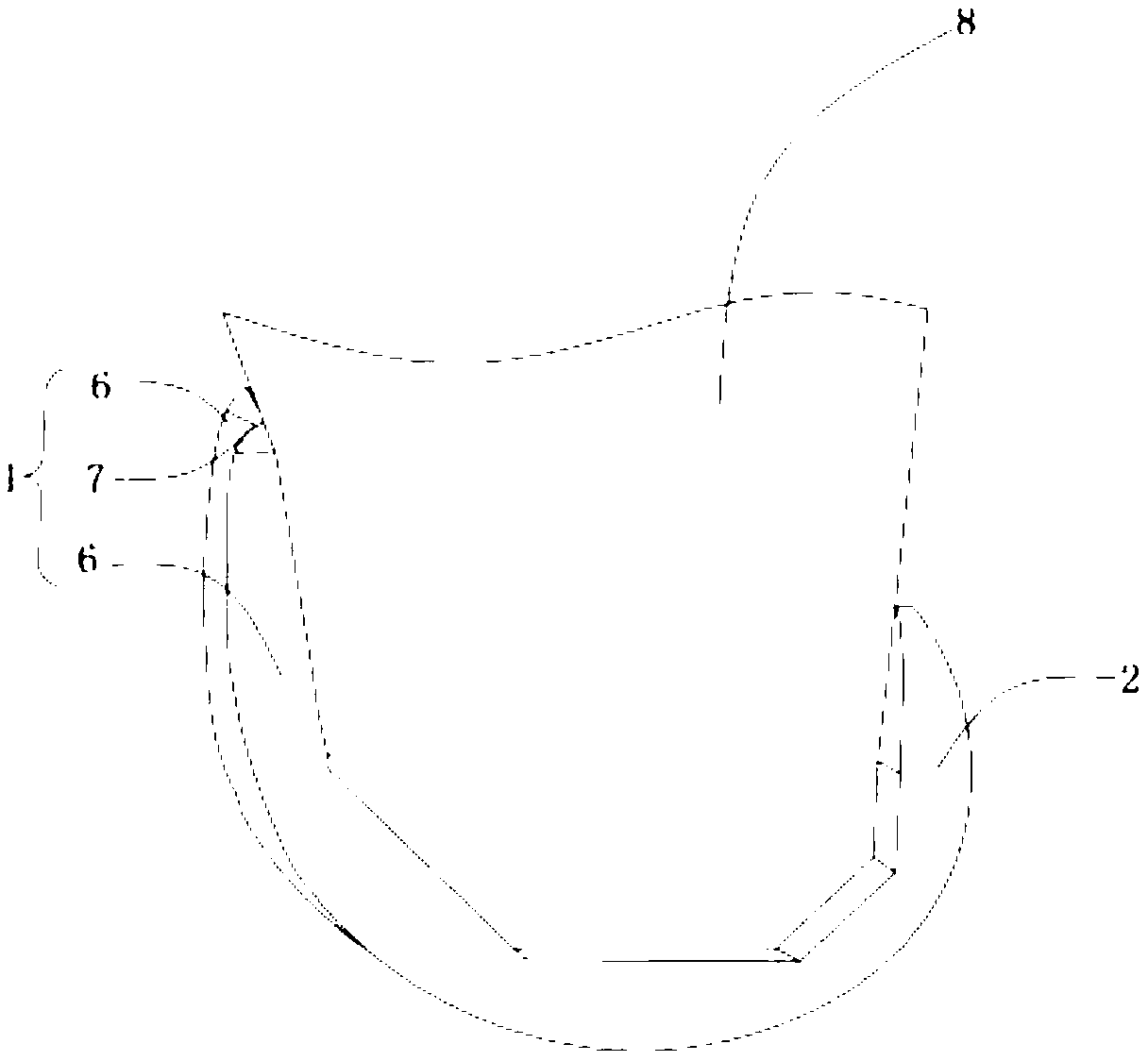
[0026] Such as figure 1 a and figure 1 As shown in b, this embodiment includes: the anterior condyle 1, the articular surface of the first femur 2, the articular surface of the second femur 3 and the insertion block 4, wherein: the articular surface 2 of the first femur and the articular surface 3 of the second femur Arranged side by side and connected with the anterior condyle 1 on the other side to form a U-shaped structure, an insertion block 4 is provided between the anterior condyle 1 and the articular surfaces 2 and 3 of the first and second femurs, and the insertion block 4 One end surface is located in the middle of the anterior condyle 1, the other end is located in the middle of the first and second femoral articular surfaces 2, 3, and the inner side of the anterior condyle 1 is provided with a strength increasing component 5.

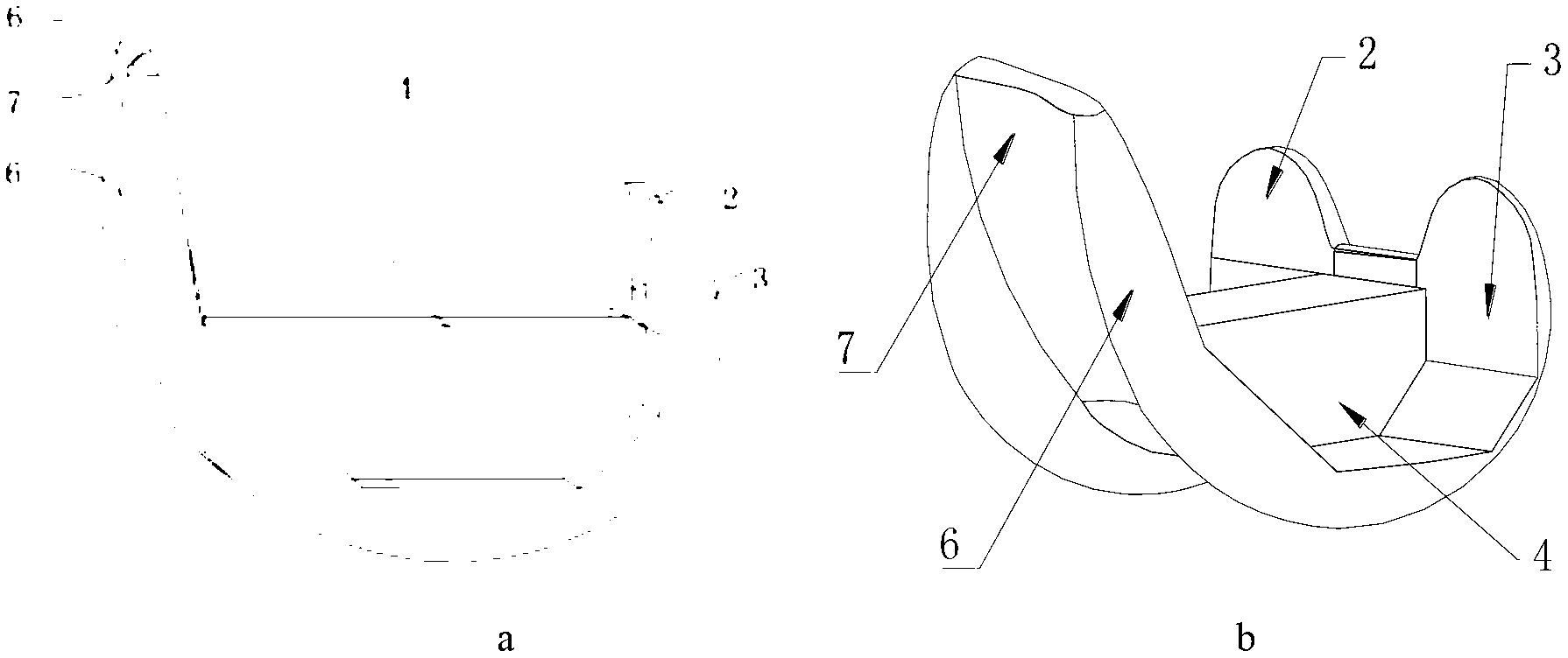
[0027] Such as image 3 , Figure 4 As shown, the structure of the strength increasing part 5 is a semi-conical structure, the bottom dia...


PUM


Abstract

The invention relates to an artificial knee-joint thighbone which belongs to the technical field of prosthesis. The artificial knee-joint thighbone comprises a preartis, a first thighbone joint face, a second thighbone joint face and an insertion block. The first and second thighbone joint faces are parallely arranged on one side and connected with the preartis on the other side to form a gap structure. The insertion block is arranged between the preartis and the first and second thighbone joint faces. One end of the insertion block is located in the middle of the preartis while the other end of the insertion block is located in the middle of the first and second thighbone joint faces. The preartis is in a corrugate structure and comprises two wave crests and a pulley groove in the trough between the wave crests. A strength enhancing part is arranged inside the side face of the preartis. According to the invention, a concave design of the pulley groove is adopted for the preartis of the thighbone, so that the preartis is relatively thinner, and the osteotomy amount of the preartis is reduced to better meet the anatomical features of the thighbone and improve match of patella articular surface and match of force line of lower limbs of a human body. Meanwhile, the strength enhancing part is arranged between the pulley groove of the preartis and the thighbone interface of the human body to enhance the thickness of the pulley groove, so as to ensure the strength of the preartis. The shape and the structure of the artificial knee-joint thighbone are more suitable for patients, and the morbidity of anterior knee pain is reduced.

Description

technical field [0001] The invention relates to a device in the field of prostheses, in particular to an artificial knee joint femur. Background technique [0002] There are many types of artificial knee joint designs in the field of clinical medical engineering. At present, the artificial knee joint prostheses used in China are mainly designed by foreign countries. Usually, the artificial knee joint prosthesis includes a femoral part of the knee joint fixed on the distal part of the femur, and a tibial part fixed on the proximal part of the tibia. A spherical or ellipsoidal convex sliding surface is formed on the rear central sliding part of the femur of the knee joint, and a spherical or ellipsoidal concave part is formed on the rear central sliding part of the tibia tray. The convex sliding surface and the concave sliding surface fit together when the knee is bent, and rotate when sliding backward, thereby increasing the range of motion. The femur of the knee joint dire...

Claims


Application Information

Patent Timeline
IPC IPC(8): A61F2/38
Inventor 吴海山王建平曹庆宏赵辉金航军沈陆
Owner THYTEC SHANGHAI
Why Eureka
Try Eureka