Handle of turning tool of milling and turning compound processing center

A composite machining center, turning tool holder technology, applied in metal processing equipment, metal processing mechanical parts, manufacturing tools, etc., can solve the problems of large effective space and isolation, achieve small effective space, reduce production costs, and improve processing. The effect of efficiency

Inactive Publication Date: 2013-05-01
黑龙江光大数控机床有限责任公司
View PDF5 Cites 4 Cited by
  • Summary
  • Abstract
  • Description
  • Claims
  • Application Information

AI Technical Summary

Problems solved by technology

[0003] The present invention aims at the problem that the oil circuit tool handle used in the existing milling and turning compound machining center needs a separate tool holder and takes up a large effective working space, and provides a turning tool tool handle of the milling and turning compound machining center

Method used


Image

  • Handle of turning tool of milling and turning compound processing center
  • Handle of turning tool of milling and turning compound processing center
  • Handle of turning tool of milling and turning compound processing center

Examples


specific Embodiment approach 1

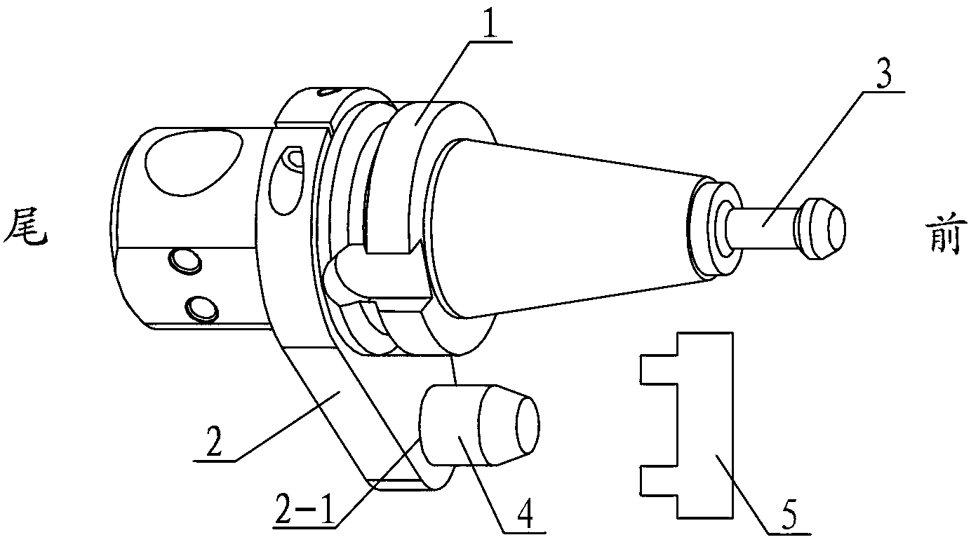
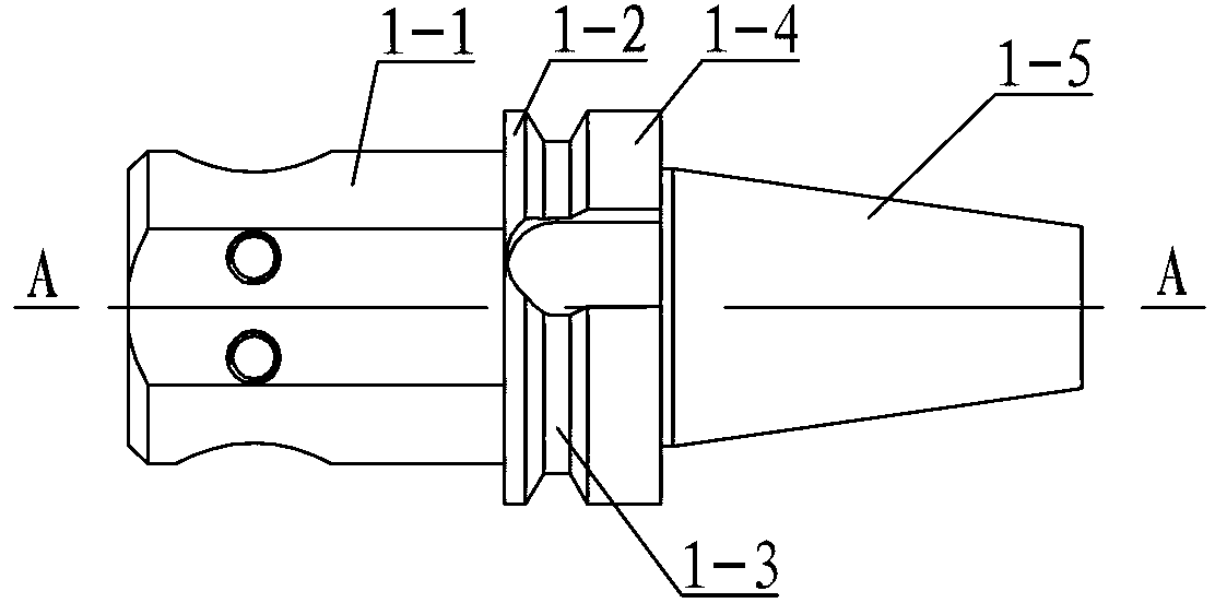
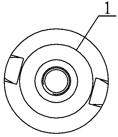
[0007] Specific implementation mode one: combine Figure 1 to Figure 7 To illustrate this embodiment, the turning tool holder of the milling and turning compound machining center in this embodiment includes a handle main body 1, a positioning sleeve 2, a pull stud 3, a positioning bolt 4 and a fixed stopper 5, and the main body of the tool holder 1 is composed of a cylindrical section 1- 1. Positioning section 1-2, empty knife section 1-3, flange section 1-4 and cone 1-5, cylindrical section 1-1, positioning section 1-2, empty knife section 1-3, flange Segments 1-4 and cones 1-5 are sequentially arranged along the same axis N-N from left to right, the large diameter end of the cones 1-5 faces the flange segment 1-4, and the outer diameter of the flange segment 1-4 is in line with the positioning segment The outer diameters of 1-2 are equal, the outer diameter of the empty knife section 1-3 is smaller than the outer diameter of the flange section 1-4, the diameter of the large ...

specific Embodiment approach 2

[0008] Specific implementation mode two: combination Figure 10 To illustrate this embodiment, the distance S between the axis N-N of the tool holder body 1 and the axis P-P of the positioning pin 4 in this embodiment is equal to the distance T between the axis K-K of the milling machine spindle and the centerline W-W of the fixed block 5 . Other components and connections are the same as those in the first embodiment.

specific Embodiment approach 3

[0009] Specific implementation mode three: combination figure 2 The present embodiment will be described. The outer diameter of the hollow segment 1-3 of the present embodiment is 10 mm to 10.5 mm smaller than the outer diameter of the flange segment 1-4. Other compositions and connections are the same as those in Embodiment 1 or 2.


PUM


Abstract

The invention relates to a milling and turning compound processing center, in particular to a tool handle of a turning tool of a milling and turning compound processing center, and solves the problems that an oil path tool handle adopted by the existing milling and turning compound processing center needs an independent tool rest, and the occupied effective working space is large. A cylinder section, a positioning section, an idle tool section, a flange section and a cone are made into a whole body, the center of the end surface of the cone is provided with a threaded hole, a pop rivet is arranged at the front end of the cone and is connected with the threaded hole through threads, a positioning sleeve is arranged on the cylinder section, one end of the positioning sleeve, which faces the positioning section, is tightly abutted to the positioning section, the lower end of the positioning sleeve is provided with a positioning pin mounting hole, a positioning pin is arranged in the positioning pin mounting hole, a fixed stop block is positioned above the positioning pin, the fixed stop block is fixedly arranged on the bottom surface of a spindle head of a milling machine, and the tail end of the cylinder section is provided with a radial through hole which is perpendicular to an axis. The tool handle is used for the turning of the milling and turning compound processing center.

Description

technical field [0001] The invention relates to a milling and turning compound machining center, in particular to a turning tool handle of the milling and turning compound machining center. Background technique [0002] When the existing milling-turning compound machining center performs turning processing, the turning tool handle used is an oil circuit tool handle, which is connected with the milling spindle of the milling-turning compound machining center. The processing principle is: the main shaft drives the oil circuit knife Shank rotation for turning. This type of oil circuit tool holder has a slow tool change speed and requires a separate tool holder, which takes up a large effective space for work, is complex in design, and high in cost, which affects the processing efficiency of the whole machine. Contents of the invention [0003] The present invention aims at the problem that the oil channel tool holder used in the existing milling and turning compound machinin...

Claims


Application Information

Patent Timeline
Patent Type & Authority Applications(China)
IPC IPC(8): B23Q3/12
Inventor 董海滨王立平余锦坤
Owner 黑龙江光大数控机床有限责任公司
Why Eureka
Try Eureka