Die of phenolic piston and manufacture method of phenolic piston

The technology of a phenolic piston and a manufacturing method, which is applied to manufacturing tools, presses and other directions, can solve problems such as poor quality of finished products, and achieve the effects of high yield, not easy to embrittle, and easy to use.

Active Publication Date: 2015-02-25
TAIZHOU WANZHOU MASCH CO LTD
View PDF7 Cites 1 Cited by
  • Summary
  • Abstract
  • Description
  • Claims
  • Application Information

AI Technical Summary

Problems solved by technology

It can be seen that in the above method, the raw materials are directly pressed into shape at one time, and the quality of the finished product is poor because there is no heat preservation treatment

Method used


Image

  • Die of phenolic piston and manufacture method of phenolic piston
  • Die of phenolic piston and manufacture method of phenolic piston
  • Die of phenolic piston and manufacture method of phenolic piston

Examples


Embodiment 1

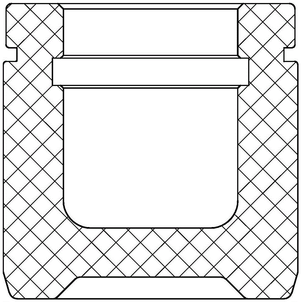
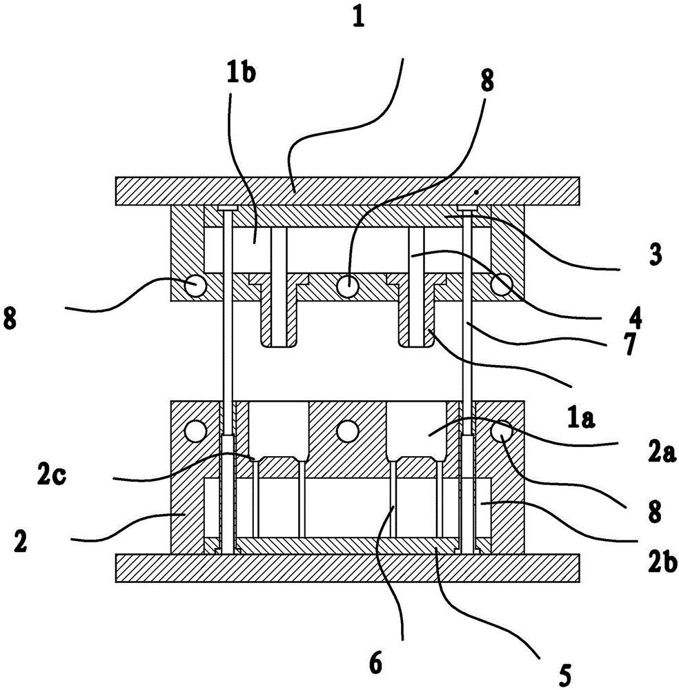
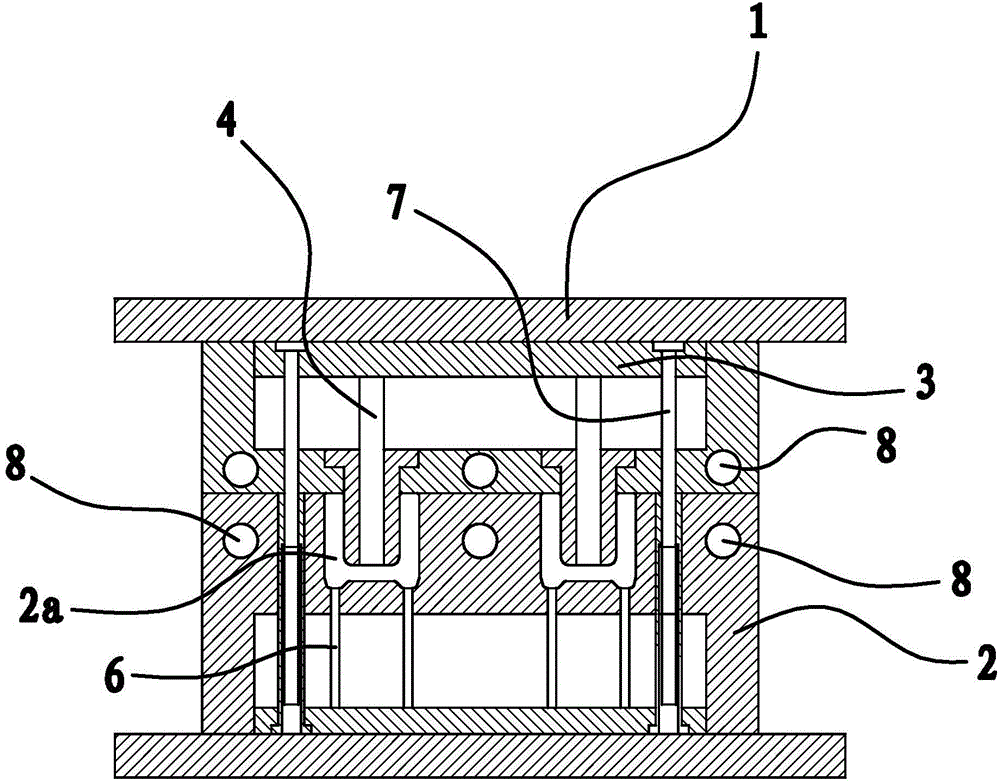
[0042] Such as figure 2 and image 3As shown, the mold of the phenolic piston includes an upper mold body 1 and a lower mold body 2. After the upper mold body 1 and the lower mold body 2 are snapped together, a molding cavity for molding the phenolic piston is formed between the two. On the upper mold body 1, there is a punch 1a that matches the inner cavity of the phenolic piston, on the lower mold body 2, there is a concave mold 2a that matches the outside of the phenolic piston, and on the convex mold 1a, there is a phenolic piston that can be adhered to it. Separate stripping piece 1, the concave mold 2a has a stripping piece 2 capable of separating the phenolic piston adhered therein. Both the upper mold body 1 and the lower mold body 2 have several heating holes 8 .

[0043] The punch 1a is in the shape of a cylinder, and the stripping part 1 includes the guide cavity 1b inside the upper mold body 1, the stripping plate 3 and the stripping rod 4 located in the guide c...

Embodiment 2

[0054] This embodiment is basically the same as the solution of Embodiment 1, the difference is:

[0055] A. Cake making: the granulated phenolic aldehyde is manufactured into a cup-shaped cake by stamping. In this embodiment, the phenolic granules are pressed into a cup-shaped cake with a pressure of 8 tons on a common punch. Then, the cake material was heated to 240°C.

[0056] B. Mold preheating: Both the upper mold body 1 and the lower mold body 2 are heated to 240°C. In this embodiment, the upper mold body 1 and the lower mold body 2 are heated to 240°C by means of electric heating. Then, the above-mentioned cake material at 240° C. is put between the upper mold body 1 and the lower mold body 2 . In this embodiment, the upper mold body 1 and the lower mold body 2 are heated to 240° C. and then kept warm for 15 minutes.

[0057] C. Mold clamping: Place the mold on the punching machine and fasten the upper mold body 1 and the lower mold body 2 with a pressure of 70 tons. ...

Embodiment 3

[0060] This embodiment is basically the same as the solution of Embodiment 1, the difference is:

[0061] A. Cake making: The granulated phenolic formaldehyde is manufactured into a cup-shaped cake by stamping. In this embodiment, the phenolic granules are pressed into a cup-shaped cake with a pressure of 6 tons on a common punch. Then, the cake material was heated to 200°C.

[0062] B. Mold preheating: Both the upper mold body 1 and the lower mold body 2 are heated to 200°C. In this embodiment, the upper mold body 1 and the lower mold body 2 are heated to 200°C by means of electric heating. Then, the above-mentioned 200° C. cake material is put between the upper mold body 1 and the lower mold body 2 . In this embodiment, the upper mold body 1 and the lower mold body 2 are heated to 200° C. and then kept warm for 10 minutes.

[0063] C. Mold closing: place the mold on the punching machine and fasten the upper mold body 1 and the lower mold body 2 through a pressure of 60 ton...


PUM


Abstract

The invention provides a die of a phenolic piston and a manufacture method of the phenolic piston, and belongs to the technical field of dies, which solves the problem of poor quality of the existing phenolic piston finished product. The die of the phenolic piston comprises an upper die body and a lower die body, wherein a plurality of heating holes are formed in the upper die body and the lower die body, and are used for directly carrying out electric heating. The upper die body and the lower die body are respectively provided with a material stripping piece, so the phenolic piston is prevented from being adhered on the die, and the stripping stability is high. The manufacture method comprises the following steps of punching cakes, heating the die, closing the die and baking, wherein the upper die body and the lower die body are directly heated, after a blank of the phenolic piston is formed, and temperature is maintained by baking, so the internal performance of the phenolic piston is further improved, the strength is higher, and the phenolic piston is not easy to brittle.

Description

technical field [0001] The invention relates to a mold, in particular to a mold of a phenolic piston and a method for making a phenolic piston using the mold. Background technique [0002] The piston works under the conditions of high temperature, high pressure, high speed and poor lubrication. The piston is directly in contact with high-temperature gas, and the instantaneous temperature can reach more than 2500K. Therefore, the heat is severe, and the heat dissipation condition is poor, so the temperature of the piston is very high when it is working, and the top is as high as 600-700K, and the temperature distribution is very uneven; the top of the piston bears The gas pressure is very high, especially the power stroke pressure is the highest, the gasoline engine is as high as 3-5MPa, and the diesel engine is as high as 6-9MPa, which makes the piston impact and bear the effect of side pressure; the piston moves in the cylinder at a very high speed (8 ~12m / s) reciprocating...

Claims


Application Information

Patent Timeline
Patent Type & Authority Patents(China)
IPC IPC(8): B30B15/02B30B15/34B30B15/32
Inventor 施剑波
Owner TAIZHOU WANZHOU MASCH CO LTD
Why Eureka
Try Eureka