
Stepped ultrasonic impact needle device and application thereof

An ultrasonic impact and step-type technology, which is applied in the field of impact pins where ultrasonic impact eliminates stress on the surface of certain materials or in the heat-affected zone of welding. problems, to achieve high-efficiency residual tensile stress, increase impact velocity, and reduce energy loss

Inactive Publication Date: 2013-05-01
天津天东恒科技发展有限公司
View PDF1 Cites 1 Cited by
  • Summary
  • Abstract
  • Description
  • Claims
  • Application Information

AI Technical Summary

Problems solved by technology

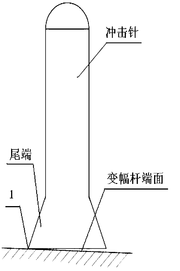
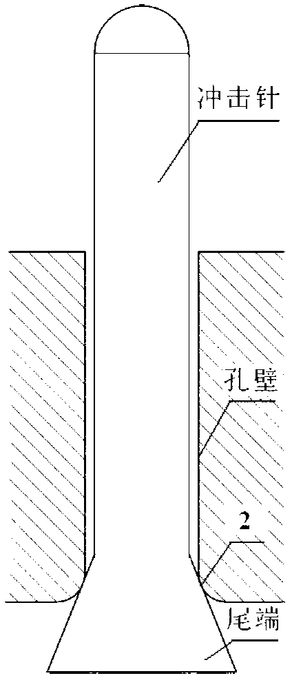
[0004] Most of the impact pin needles in the prior art are designed with a tipped structure at the tail. On the one hand, during the working process, the impact needle and the impact needle holder collide at the muzzle, which greatly reduces the impact speed of the impact needle; in addition, the tail During the collision process of the belt tip structure with the transducer, the impact needle is likely to be skewed due to the uneven force, both of which will reduce the depth of the stress layer generated by the ultrasonic impact, which has a significant impact on the impact effect

Method used


Image

  • Stepped ultrasonic impact needle device and application thereof
  • Stepped ultrasonic impact needle device and application thereof
  • Stepped ultrasonic impact needle device and application thereof

Examples


Embodiment 1

[0031] Example 1 The step-shaped impact needle is matched with the extension head of the pit-shaped impact needle

[0032] as attached Figure 5As shown, the structure is composed of impact needle seat 1, impact needle 2 and impact needle extension head 3 with a pit. The shape of the impact needle seat is a cylindrical structure, and the muzzle is cone-shaped. And on the outer circumference, there is a protrusion for loading and unloading, the opening end is matched with the shell of the ultrasonic impact gun (not shown in the figure), and then fixed with a flange, and the loading and unloading protrusion 5 plays a fixed role between the flange and the shell of the impact gun; The other end is sealed, which is the muzzle end, and is provided with baffles 7 and 8, on which there is a round hole matched with the impact needle. The diameter of the stepped cylinder (D is 1.3d; l is 0.2L) reduces friction when the impact needle collides with the muzzle of the impact needle seat. B...

Embodiment 2

[0033] Example 2 The step-type impact needle is matched with the extension head of the flat-type impact needle

[0034] as attached Figure 6 As shown, the structure is composed of impact needle seat 1, impact needle 2 and impact needle extension head 3 with a pit. The shape of the impact needle seat is a cylindrical structure, and the muzzle is cone-shaped. And on the outer circumference, there is a protrusion for loading and unloading, the opening end is matched with the shell of the ultrasonic impact gun (not shown in the figure), and then fixed with a flange, and the loading and unloading protrusion 5 plays a fixed role between the flange and the shell of the impact gun; The other end is sealed, which is the muzzle end, and is provided with baffles 7 and 8, on which there is a round hole matched with the impact needle. The diameter of the needle is a stepped cylinder (D is 1.3d; l is 0.1L), which reduces the friction when the impact needle collides with the muzzle of the ...


PUM

PropertyMeasurementUnit
sizeaaaaaaaaaa

Abstract

The invention discloses a stepped ultrasonic impact needle device and the application thereof; an impact needle and a muzzle try to have rigid collision by changing the shape of the impact needle, so that the problem of the prior art that the speed of the impact needle is reduced caused by that quite great friction force is produced when the impact needle with a pin has collision with an impact needle base muzzle is solved. Meanwhile, the collision method of the impact needle and an extended head of the impact needle is changed, point contact replaces surface contact, so that the stress direction of a contact surface when in collision is consistent with the axial direction of the impact needle, the impact needle does not easily deviate, and the ultrasonic impact efficiency and stability can also be improved.

Description

technical field [0001] The present invention relates to the use of an ultrasonic impact tool accessory, more specifically, to an impact needle for eliminating stress on the surface of certain materials or in the heat-affected zone of welding by ultrasonic impact. The impact needle can significantly improve the efficiency of ultrasonic impact and produce The deeper compressive stress layer significantly improves the strength, corrosion resistance and fatigue life of the material. Background technique [0002] During the processing of the welded structure, due to the action of the welding heat cycle, local uneven thermoplastic deformation and phase transformation of the welded joint are caused, resulting in self-equilibrium welding residual stress, which reduces the performance of the welded joint. distribution of residual stress to improve its performance. Because the method is flexible and efficient, it has a wide range of applications. It can be applied not only in the man...

Claims


Application Information

Patent Timeline
Patent Type & Authority Applications(China)
IPC IPC(8): C21D10/00
Inventor 王东坡吴良辰黄超张涛柳阳王颖
Owner 天津天东恒科技发展有限公司
Learn More