Rotary drilling rig and follow-up rack thereof
A technology of rotary drilling rig and follower frame, which is applied in the directions of earthwork drilling, drilling equipment, support device, etc., can solve the problems of difficulty in adjusting the angle of the sliding ear of the follower frame, and achieve easy implementation, improve disassembly and assembly efficiency, Easy-to-use effects
- Summary
- Abstract
- Description
- Claims
- Application Information
AI Technical Summary
Problems solved by technology
Method used
Image

Examples
Embodiment 1
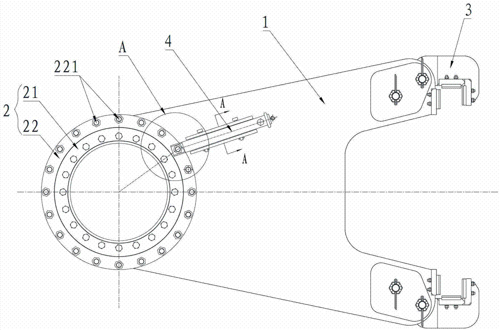
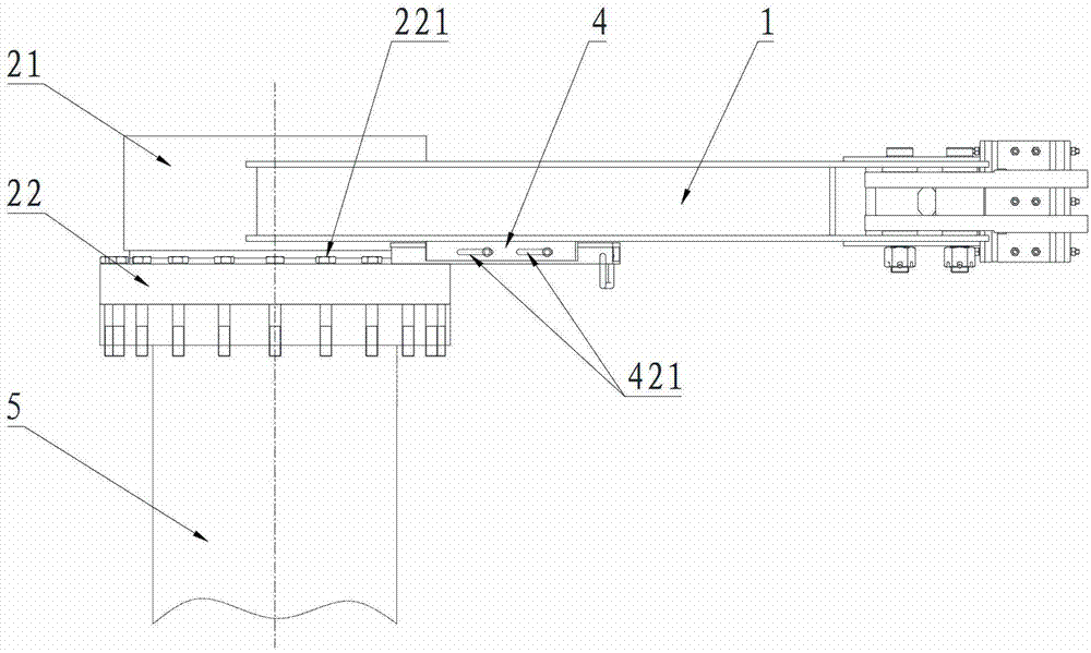
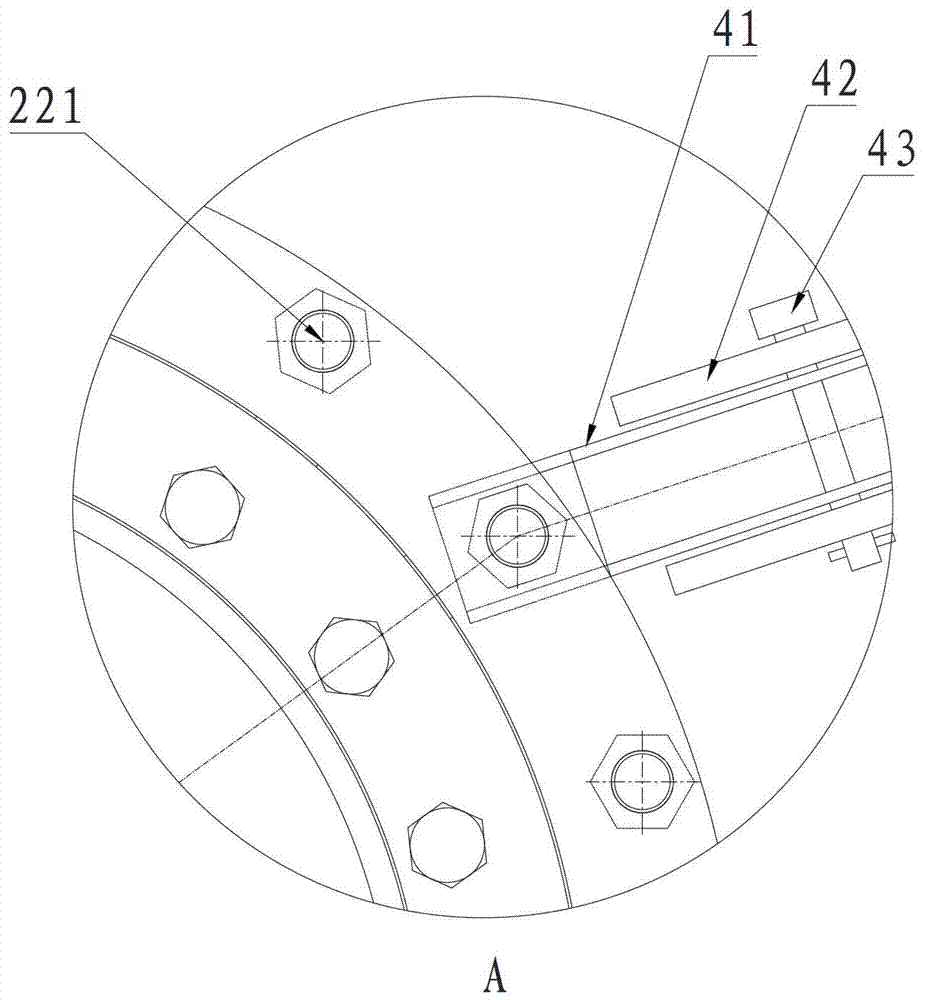
[0042] Figure 1 to Figure 4It is the related drawings of this embodiment. As shown in the figure, this embodiment discloses a follower frame of a rotary drilling rig. The follower frame includes a frame body 1 and slewing bearings arranged at both ends of the frame body 1 2 and sliding lug 3, the outer ring 22 of the slewing bearing 2 is fixedly connected with the drill pipe 5 of the rotary drilling rig through bolts 221, the inner ring 21 of the slewing bearing 2 is fixed on the frame body 1, and the frame body 1 is also equipped with a The rotation restricting device restricts the relative rotation of the outer ring 22 and the frame body 1 . In this embodiment, the rotation restraining device is a latch device 4 that can selectively catch the bolt 221. The latch device 4 includes a guide rail 42, a latch 41 and a locking screw. The guide rail 42 includes two parallel shafts fixed on the main body. Plate-shaped structure, strip-shaped holes 421 are provided along its length...
Embodiment 2
[0045] Figure 5 and Image 6 That is the relevant drawings of this embodiment. Compared with Embodiment 1, the rotation restraint device of the follower frame described in this embodiment is different. As shown in the figure, the rotation restraint device in this embodiment is set on the frame The body 1 and the outer circle of the outer ring 22 constitute the set screw device 6 of the friction pair. The set screw device 6 includes a mounting seat 61 and a set screw 62, the mounting seat 61 is an arc-shaped block structure fixedly arranged on the frame body 1, and the mounting seat 61 is provided with a screw corresponding to the set screw 62. The set screw 62 is screwed into the screw hole and passes through the screw hole against the outer circle of the outer ring 22 . The operator can lock the outer ring 22 by turning the set screw 62 to limit the relative rotation between the outer ring 22 and the follower frame, or disengage from the outer circle of the outer ring 22 t...
Embodiment 3
[0049] Figure 7 to Figure 12 That is the relevant drawings of this embodiment. Compared with Embodiment 1, this embodiment differs in that the rotation restraint device is different. As shown in the figure, the rotation restraint device in this embodiment is arranged on the frame body 1 and the outer The upper end surface of the ring 22 constitutes the pressure plate device 7 of the friction pair. The pressing plate device 7 includes a pressing plate 71 hinged on the frame body 1 and a driving bolt 72 for driving the pressing plate 71 to be tightly pressed against the end surface of the outer ring 22 .
[0050] In this embodiment, there are three ways to connect the pressing plate 71 and the driving bolt 72:
[0051] First, the middle part of the pressure plate 71 is hinged on the frame body 1 through the hinge point 75, one end of the pressure plate 71 rests on the end face of the outer ring 22, the other end of the pressure plate 71 is connected with the driving bolt 72, t...
PUM
 Abstract
Description
Claims
Application Information
 - Generate Ideas
- Intellectual Property
- Life Sciences
- Materials
- Tech Scout
- Unparalleled Data Quality
- Higher Quality Content
- 60% Fewer Hallucinations
Browse by: Latest US Patents, China's latest patents, Technical Efficacy Thesaurus, Application Domain, Technology Topic, Popular Technical Reports.
© 2025 PatSnap. All rights reserved.Legal|Privacy policy|Modern Slavery Act Transparency Statement|Sitemap|About US| Contact US: help@patsnap.com