Ammonia spraying and mixing system for coal-fired flue gas SCR denitration technology

A kind of technical equipment, coal-fired flue gas technology, applied in the direction of lighting and heating equipment, dispersed particle separation, chemical instruments and methods, etc., can solve the problems that cannot reduce the difficulty of ammonia injection adjustment, increase installation costs, increase system pressure drop, etc., Achieve the effect of optimizing the mixing effect of ammonia nitrogen, reducing energy loss, and improving the mixing intensity of vortex

Inactive Publication Date: 2010-05-19
ZHEJIANG UNIV
View PDF0 Cites 11 Cited by
  • Summary
  • Abstract
  • Description
  • Claims
  • Application Information

AI Technical Summary

Problems solved by technology

At present, in commercial application, the ammonia injection device in the form of a grid is generally used. The ammonia injection grid method adopts multi-point injection zone adjustment. Due to the large number of reductant ammonia injection pipes and nozzle holes, it makes its It is quite difficult to adjust in actual operation. The static mixer that must be installed in order to improve the mixing effect and shorten the mixing distance often increases the installation cost and increases the pressure drop of the system and does not reduce the adjustment difficulty of ammonia injection during operation.

Method used


Image

  • Ammonia spraying and mixing system for coal-fired flue gas SCR denitration technology
  • Ammonia spraying and mixing system for coal-fired flue gas SCR denitration technology
  • Ammonia spraying and mixing system for coal-fired flue gas SCR denitration technology

Examples


Embodiment Construction

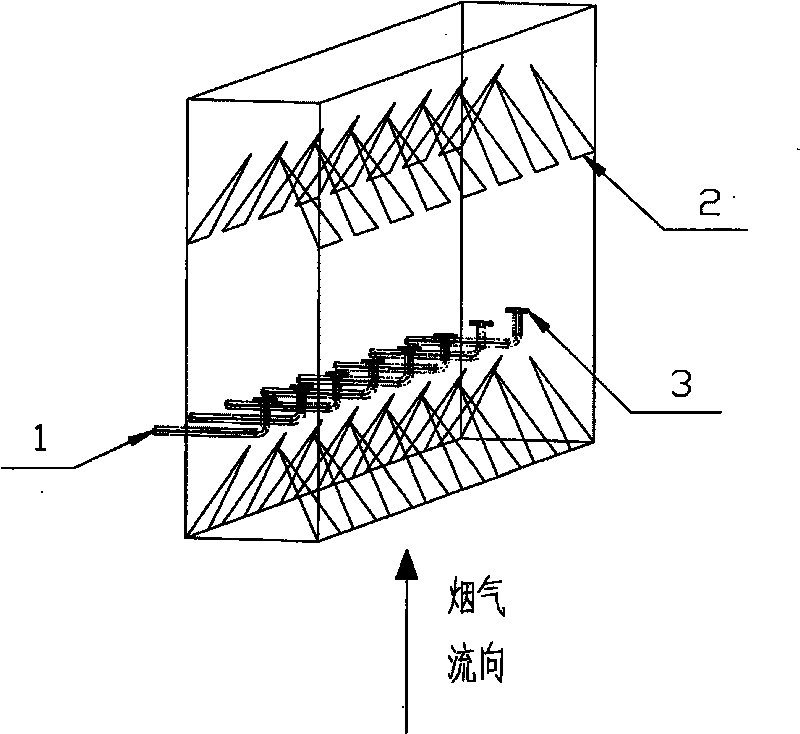
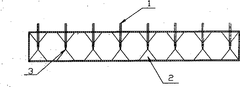
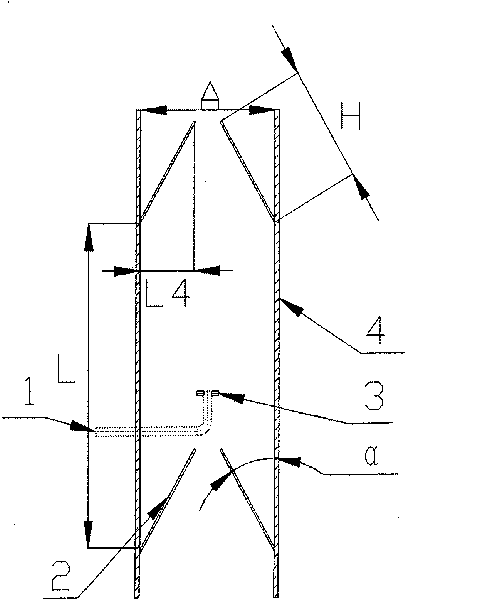
[0016] As shown in the figure, the ammonia injection mixing system used for coal-fired flue gas SCR denitrification technology equipment includes a flue, a reductant ammonia injection pipe 1, a longitudinal vortex generator 2, and a two-way nozzle 3. There are 5~ 20 reducing agent ammonia injection pipes 1, the end of each reducing agent ammonia injection pipe 1 is provided with a two-way nozzle 3, and the upstream and downstream flue walls of the two-way nozzle 3 are provided with a longitudinal vortex generator 2, and the longitudinal vortex generator 2 is composed of two rows of uniformly and symmetrically arranged longitudinal vortex generating element groups fixed on the two walls of the flue. Each row of longitudinal vortex generating element groups is composed of a plurality of longitudinal vortex generating elements. Into 30 ° ~ 60 ° angle.

[0017] Each reductant ammonia injection pipe 1 has a separate flow control system.

[0018] The shape of the longitudinal vorte...


PUM


Abstract

The invention discloses an ammonia spraying and mixing system for the coal-fired flue gas SCR denitration technology and relates to a system used for spraying reducing agent ammonia and strengthening the mixture of ammonia and flue gas. The ammonia spraying and mixing system comprises 5-20 reducing agent ammonia jet tubes with independent flow control systems and longitudinal vortex generation elements, wherein the tail end of each reducing agent ammonia jet tube is provided with a two-way nozzle which is vertical and symmetric to the flue gas stream, each longitudinal vortex generation element is a triangle, a trapezoid, a half round or a half ellipse, each longitudinal vortex generation element is connected with the flue wall and forms 30-60 degrees angle with the flue gas stream so as to form longitudinal vortex of which downstream is stable, increase the intensity of turbulent flow and enhance the mixture of reducing agent ammonia and glue gas. The device has the following advantages: 1) the stable longitudinal vortex is formed, the mixing intensity of vortex is increased, and the mixing effect of ammonia and nitrogen is optimized; 2) the number of the ammonia jet tubes is reduced, the ammonia-spraying regulation difficulty is lowered; and 3) pressure breakdown caused by the system is relatively small and the energy loss is reduced.

Description

technical field [0001] The invention relates to environmental protection technology, in particular to an ammonia injection mixing system equipped with coal-fired flue gas SCR denitrification technology. Background technique [0002] In today's society, the emission of nitrogen oxides will cause a series of problems such as ozone layer destruction, acid rain and atmospheric smoke formation, which will cause serious harm to human health. From a global perspective, the nitrogen oxides produced by fuel combustion, especially coal combustion, are one of the main sources of nitrogen oxides in the atmosphere. Among many denitrification technologies, selective catalytic reduction (SCR) denitrification technology has been widely used commercially due to its simple device structure, no by-products, convenient operation, high reliability, and high denitrification efficiency. Its main principle is to spray the reducing agent ammonia into the flue gas at 280°C to 420°C and mix it evenly...

Claims


Application Information

Patent Timeline
Patent Type & Authority Applications(China)
IPC IPC(8): B01D53/90B01D53/56F23J15/04
Inventor 高翔骆仲泱岑可法倪明江钟毅吴卫红张涌新施正伦周劲松方梦祥余春江王树荣程乐鸣王勤辉
Owner ZHEJIANG UNIV
Why Eureka
Try Eureka