Three-dimensional light distribution detection apparatus for optical focus area

A focus area and light intensity distribution technology, applied in the optical field, can solve the problems of high positioning requirements for machining, inconvenient adjustment and use, and high requirements for devices, and achieve the effect of low positioning requirements for machining, convenient adjustment and use, and improved measurement accuracy

Inactive Publication Date: 2009-07-08
HANGZHOU DIANZI UNIV
View PDF1 Cites 12 Cited by
  • Summary
  • Abstract
  • Description
  • Claims
  • Application Information

AI Technical Summary

Problems solved by technology

This detection system has considerable advantages, but there are still some deficiencies: 1) The focusing objective lens cannot be displaced during the operation of the device, and the optical fiber probe is driven by the piezoelectric ceramic scanner to perform detection and scanning, and at the same time the patent claim 1 The objective lens is required to be placed at the position where the focal spot of the objective lens falls on the probe tip of the fiber optic probe. Due to the limited scanning range of the piezoelectric ceramic scanner, the above technical scheme makes it difficult to adjust the scanning position of the detection device. Inconvenient; 2) The axial position adjustment of the fiber optic probe is mediated through a manual or electric adjustment frame connected to the piezoelectric ceramic scanner. Two movable parts are connected, and the mechanical positioning characteristics of the manual or electric adjustment frame are not as good as Piezoelectric ceramic scanners, in piezoelectric ceramic scanners, the mechanical positioning characteristics of manual or electric adjustment frames have an important impact on the measurement accuracy, which is equivalent to the scanning reference of high-precision scanning mechanisms is established on low-precision adjustment frames The measurement accuracy has a great influence, which reduces the measurement accuracy of the light intensity distribution; 3) This detection device has high requirements for the mechanical processing and positioning of the system structure, complex structure, and high device requirements. For example, in patent claim 1, it is required The optical axis of the light source is at an angle of 45°, and the line connecting the center point of the reflective surface of the beam splitter and the tip of the fiber optic probe is a vertical line perpendicular to the optical axis of the laser light source. The reflective surface of the beam splitter should form a 45° angle with the incident light, and a series of structural requirements and device requirements, such as a camera with a monitor, increase the difficulty of the detection device and limit the scope of detection applications.

Method used


Image

  • Three-dimensional light distribution detection apparatus for optical focus area

Examples


Embodiment Construction

[0021] The present invention will be further described below in conjunction with drawings and embodiments.

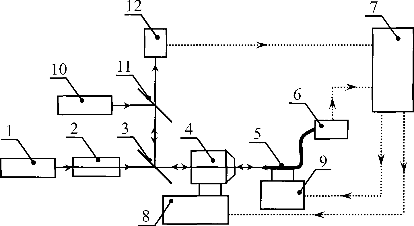
[0022] Such as figure 1 The three-dimensional light intensity distribution detection device in the optical focus area includes a system light source 1, a beam shaper 2, a spectral beam splitter 3, an objective lens 4, an optical fiber probe 5, a photoelectric sensor 6, an analysis control unit 7, a one-dimensional mobile platform 8, and a three-dimensional mobile platform. Platform 9 , monitoring light source 10 , beam splitter 11 and image collector 12 . The beam shaper 2, the spectral beam splitter 3, and the objective lens 4 are successively arranged on the optical path of the output beam of the system light source 1, the needle tip of the fiber probe 5 is set corresponding to the beam output direction of the objective lens 4, and the light energy output end of the fiber probe 5 is connected to the photoelectric Sensor 6 is connected. The one-dimensional mobile pla...


PUM


Abstract

The invention relates to a device for detecting three-dimensional light intensity distribution in an optical focus region. The prior art adopts connection between an adjusting rack and a piezoelectric ceramics scanner, so measurement precision is influenced, and an optical machine has high positioning requirement and large difficulty of device realization. In the invention, a light source is shaped by a light beam shaper and is focused to form a tested focus by a field lens; a one-dimensional movable platform drives the field lens to realize axial movement for testing and coarse positioning; a three-dimensional movable platform drives a fiber probe to carry out three-dimensional scanning in a focus region to realize the detection of the three-dimensional light intensity distribution; a monitoring optical path consisting of a monitoring light source, a spectroscope and an image acquirer is coupled to a tested optical path by a spectrum spectroscope to monitor a device adjusting and testing process; and an analysis and control unit carries out analysis and control coordination on the whole testing process and a result. The device has the characteristics of low requirement on mechanical processing and positioning, simple system composition, low requirement on devices, high measuring precision, convenient use, and the like.

Description

technical field [0001] The invention belongs to the field of optical technology, and relates to a light intensity distribution detection device, in particular to a three-dimensional light intensity distribution detection device in an optical focus area. It is mainly used in the evaluation of optical properties, the research of optical information transmission characteristics, the detection of the characteristics of focusing optical systems, and the fields of optical storage, lithography technology, and microscopic imaging. technical background [0002] The demand for three-dimensional light intensity distribution detection in the optical focal area widely exists in the evaluation of optical properties, the study of optical information propagation characteristics, the detection of characteristics of focusing optical systems, and the fields of optical storage, lithography, and microscopic imaging. For example, in the field of optical storage, the focusing characteristics of th...

Claims


Application Information

Patent Timeline
Patent Type & Authority Applications(China)
IPC IPC(8): G01J1/42G01J1/08G01J1/04
Inventor 高秀敏郭舒文王健
Owner HANGZHOU DIANZI UNIV
Why Eureka
Try Eureka