
High pressure common rail fuel metering valve

A fuel metering valve, high-pressure common rail technology, applied in fuel injection pumps, fuel injection devices, engine components, etc., can solve the problems of fuel circulation buffer, low fuel circulation buffer strength, complex processing technology, etc., to reduce processing difficulty and Cost, stable fuel throughput, and effect of improving structural strength

Inactive Publication Date: 2013-05-01
江苏富山生物科技有限公司
View PDF11 Cites 2 Cited by
  • Summary
  • Abstract
  • Description
  • Claims
  • Application Information

AI Technical Summary

Problems solved by technology

[0004] However, the ring channel on the valve housing belongs to the inner ring channel, and the processing technology is complicated; the valve piston is tubular, and because the tube wall is thin, the upper throttle hole, the processing technology is complicated and difficult to control; in addition, when the valve piston is in the electromagnetic operation assembly Driven to move to a certain axial position in the valve housing, when the valve core rotates in the valve housing, the corresponding position of the throttle hole of the valve piston and the inflow hole of the valve housing directly affects the fuel throughput in the throttle hole ( When the orifice is facing the inflow hole of the valve housing, the fuel flux generated by the orifice is the largest, and the fuel circulation buffer force is small), which makes the fuel flow in the orifice unstable, and the fuel flow cannot always be effective ground buffer

Method used


Image

  • High pressure common rail fuel metering valve
  • High pressure common rail fuel metering valve
  • High pressure common rail fuel metering valve

Examples


Embodiment Construction

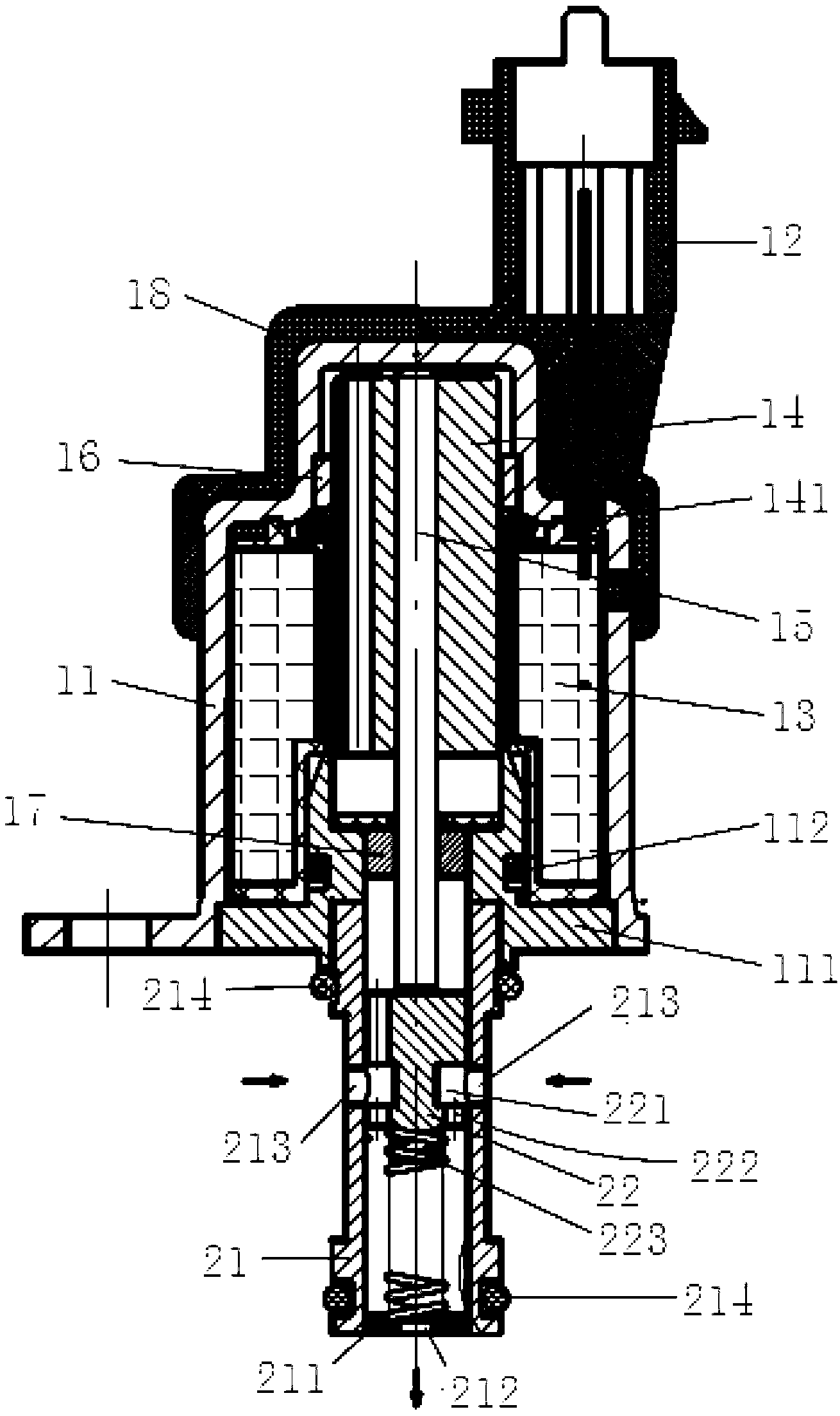
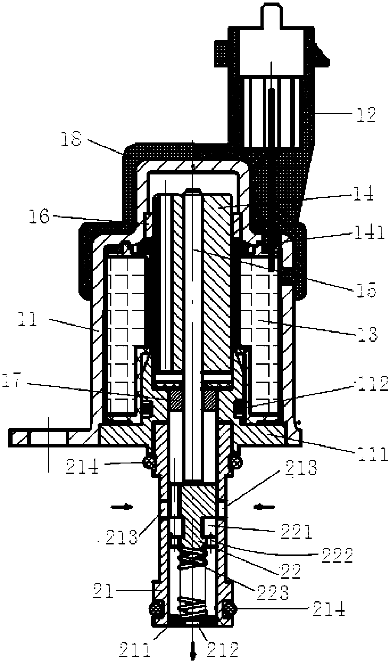
[0023] A specific embodiment of the present invention will be described in detail below in conjunction with the accompanying drawings, but it should be understood that the protection scope of the present invention is not limited by the specific embodiment. It should be understood that the "upper", "lower", "left", "right", "front" and "reverse" mentioned in the following embodiments of the present invention are all based on the directions shown in the figures, These words used to limit the direction are only for convenience of description, and do not mean to limit the specific technical solution of the present invention.

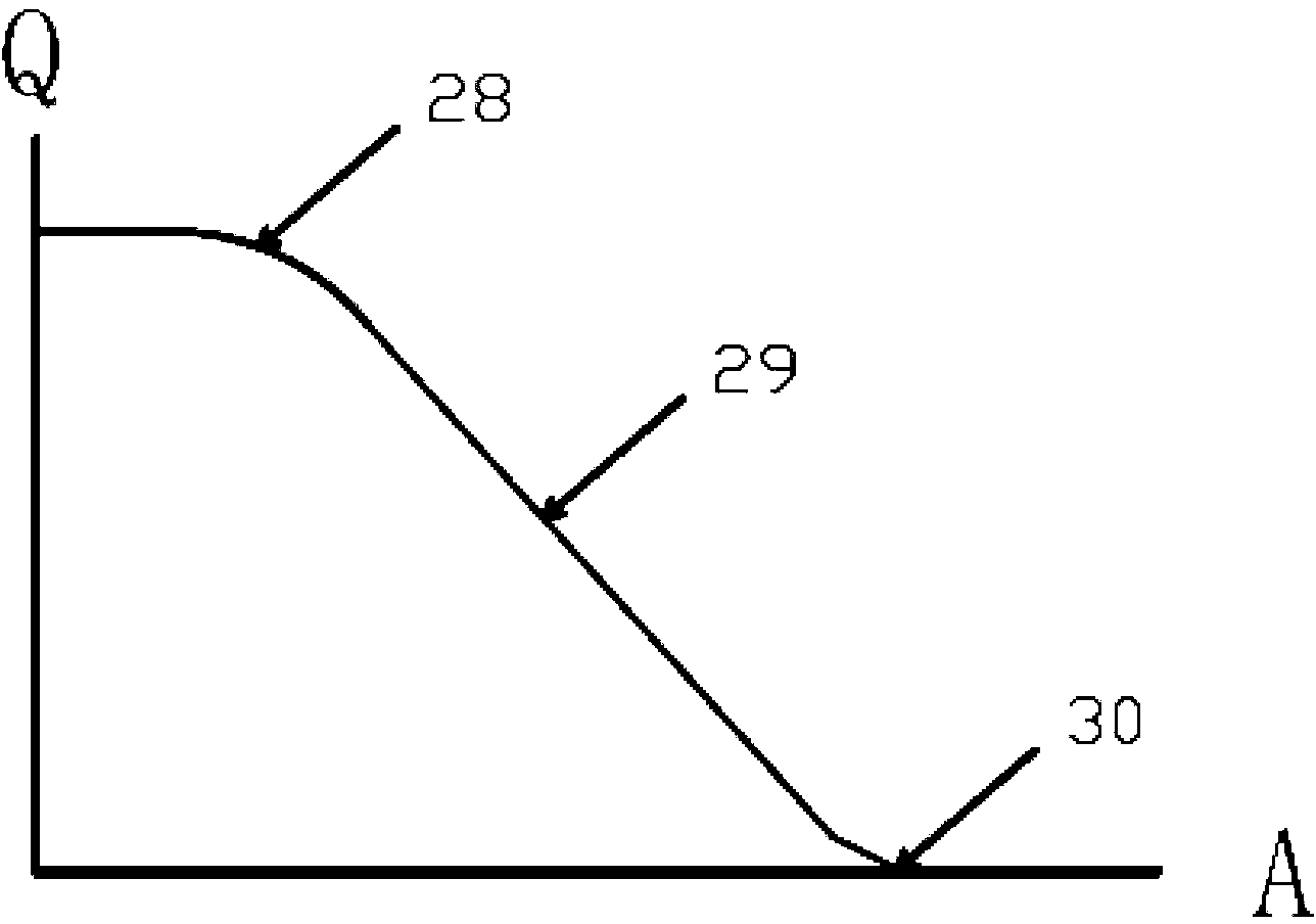
[0024] The high-pressure common rail fuel metering valve of the present invention reduces the processing difficulty and cost of the valve housing by processing the radial annular groove that cooperates with the radial orifice to change the oil inlet cross-sectional area on the outer circumference of the cylindrical valve piston. Increased structural strength...


PUM


Abstract

The invention discloses a high pressure common rail fuel metering valve, which comprises an electromagnetic operating component and a regulating valve driven by the electromagnetic operating component, wherein the regulating valve comprises a valve shell and a valve piston; the pipe wall of the valve shell is provided with opposite radial orifices which penetrate through an inner cavity; the lower end of the valve shell is provided with a spring seat which is provided with a flow port; the valve piston is columnar, and the outer circumference of the valve piston is provided with radial annular grooves matched with the radial orifices to change an open area; and the valve piston is axially provided with flow circular holes communicated with the radial annular grooves. According to the high pressure common rail fuel metering valve, the radial annular grooves matched with the radial orifices to change the fuel inlet sectional area are machined on the outer circumference of the columnar valve piston, the machining process is simple, and the machining difficulty and cost are reduced; and in addition, compared with the conventional tubular valve piston, the columnar valve piston has the advantages of improving structural strength and reducing machining difficulty and cost.

Description

technical field [0001] The invention relates to the field of engines, in particular to a high-pressure common rail fuel metering valve. Background technique [0002] The fuel metering valve is installed at the oil inlet position of the high-pressure oil pump, and is used to adjust the fuel supply and fuel pressure value, and its adjustment requirements are controlled by the ECU. quantity. [0003] The fuel metering valve includes: an electromagnetic operating assembly and a regulating valve driven by the electromagnetic operating assembly. The valve casing of the regulating valve has a ring channel, and an inflow hole communicating with it is opened on the ring channel. The valve piston is tubular. The inner cavity is filled with oil, and its circumference is provided with an orifice connected with the inner cavity. This structure enables the fuel to be output from the outlet of the front-stage delivery pump of the system, through the inflow hole and ring channel on the val...

Claims


Application Information

Patent Timeline
IPC IPC(8): F02M59/46
Inventor 李正富
Owner 江苏富山生物科技有限公司
Learn More