
Double-cold source fresh air handling unit

A fresh air unit and dual cold source technology, applied in the field of processing equipment, can solve the problems of small cooling load, harsh wet environment, moldy and spoiled indoor items, etc., to achieve energy-saving operation, moderate fresh air temperature, and avoid indoor humidity Effect

Active Publication Date: 2013-05-01
GUANGDONG PROVINCIAL ACAD OF BUILDING RES GRP CO LTD
View PDF4 Cites 10 Cited by
  • Summary
  • Abstract
  • Description
  • Claims
  • Application Information

AI Technical Summary

Problems solved by technology

[0003] Due to the transitional seasons, especially the "returning to the south" season at the turn of spring and summer in the southern region and the "huangmeitian" season in the Yangtze River Basin, the outdoor air humidity is relatively high. When the air conditioning system is running with fresh air, it cannot dehumidify because there is no chilled water supply. Sending humid outdoor air directly into the room will form a harsh humid environment indoors, which will seriously affect the quality of life and work of indoor personnel, and may cause mold and deterioration of indoor items.
In addition, even if the chiller is turned on in the transitional season to provide chilled water for the air-conditioning unit for dehumidification, the air-conditioning units in the southern region generally do not have the reheating function. If it is low, the indoor cooling load is small, and the cold air after dehumidification is sent into the room, which will make the indoor temperature too low and affect the thermal comfort of the room

Method used


Image

  • Double-cold source fresh air handling unit
  • Double-cold source fresh air handling unit

Examples


Embodiment Construction

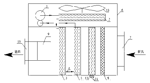
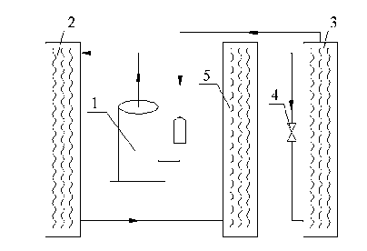
[0015] Such as figure 1 The shown double cold source fresh air unit includes a fresh air unit casing 6, and a compressor 1, a first condenser 2, a second condenser 3, a throttling device 4, an evaporator 5, an inlet Tuyere 7, filter 8, air outlet 10, chilled water supply and return pipe 11 and surface cooler 12. The compressor 1, the first condenser 2, the second condenser 3, the throttling device 4 and the evaporator 5 are sequentially connected through copper pipes to form the self-cooling system of the fresh air unit; the surface cooler 12 is supplied and returned through the chilled water pipe 11 Connect the cold source system of the external centralized air conditioner; the filter 8 is installed at the air inlet 7; superior.

[0016] The flow direction of the refrigerant in the self-cooling source system of the fresh air unit in this embodiment is as follows: figure 2 As shown, the refrigerant enters the first condenser 2 and then the second condenser 3 after being co...


PUM


Abstract

The invention relates to a double-cold source fresh air handling unit, which comprises a fresh air handling unit shell, wherein a compressor, a first condenser, a second condenser, a throttling device, an evaporimeter, an air inlet, a filter, an air outlet, a chilled water supply water return pipe and a surface air cooler are arranged in the fresh air handling unit shell; the compressor, the first condenser, the second condenser, the throttling device and the evaporimeter are connected sequentially through a copper pipe so as to form a cold source system of the fresh air handling unit; and the surface air cooler is connected with an external central air conditioning cold source system through the chilled water supply water return pipe. The double-cold source fresh air handling unit has the advantages that (1) the double-cold source fresh air handling unit is provided with the independent cold source system, in a transition season, a central air conditioning cold source stops working, and when an air conditioning ventilation system fresh air is operated in an energy-saving way, a self cold source can be applied to carry out dehumidification on fresh air, so that the phenomena of indoor moisture and mustiness are avoided; and (2) when the fresh air handling unit is used, the fed fresh air supplied in the transition season has moderate temperature, and the comfort of indoor temperature in the transition season is ensured.

Description

technical field [0001] The invention belongs to the field of refrigeration and air-conditioning equipment, and in particular relates to equipment for delivering fresh air to buildings and performing cooling, dehumidification and other treatments. Background technique [0002] With the increase of building scale, the application of central air-conditioning system is more common. However, in the transition season, the operation efficiency of the central air-conditioning system is low. In order to save energy, the mode of fresh air operation is often adopted in the transition season. When the fresh air is running, the chilled water system of the air conditioner stops running and does not provide cooling for the air conditioning unit. The air conditioning unit cannot perform heat and humidity treatment on the outdoor fresh air, and the air conditioning unit directly sends the outdoor fresh air into the room. [0003] Due to the transition season, especially the "returning to the...

Claims


Application Information

Patent Timeline
Patent Type & Authority Applications(China)
IPC IPC(8): F24F3/14F24F13/30F24F13/28
Inventor 杨仕超余鹏罗运有
Owner GUANGDONG PROVINCIAL ACAD OF BUILDING RES GRP CO LTD
Learn More