Optical imaging lens and electronic device applying same

An optical imaging lens and lens technology, which is applied in the field of optical lenses, can solve the problems affecting optical performance and imaging quality, the system length cannot be effectively shortened, and the total system length can be shortened to achieve light and thin structure design, good optical performance, and improved The effect of sensitivity

Active Publication Date: 2013-05-01
GENIUS ELECTRONICS OPTICAL XIAMEN
View PDF17 Cites 3 Cited by
  • Summary
  • Abstract
  • Description
  • Claims
  • Application Information

AI Technical Summary

Problems solved by technology

[0003] US 2011 / 0299178 patent discloses an optical imaging lens composed of four lenses, the refractive index of the first lens is negative, the refractive index of the second lens is positive, and the image side of the third lens is The area adjacent to the optical axis or the area adjacent to the circumference is concave, while the image side of the fourth lens is convex in the area adjacent to the optical axis or the area adjacent to the circumference. This design cannot effectively shorten the total length of the system while taking into account the optical performance
[0004] In addition, US 2011 / 0242683, US 2011 / 0188132, and US 2011 / 0188133 patents also disclose a four-piece optical imaging lens, the refractive power of the first and second lenses is negative, but its There is a considerable air gap between the first and second lenses, which also makes the system length unable to be shortened effectively
[0005] US 2011 / 0261471 and US 2012 / 0176687 patents also disclose a four-piece optical imaging lens. Although the refractive powers of the first and second lenses are respectively preferably positive and negative, the second lens The image side of the lens is completely concave, so there must be a considerable air gap between the second and third lenses, and the effect of shortening the total length of the system cannot be achieved
[0006] In addition, although cases such as TWI279607, US7755853, US7692877, JP2011064989, US8089704, TW201137429, JP2012042840, US20110058262, and US20120069449 each disclosed an optical imaging lens, they could not achieve the goal of shortening the overall length of the imaging system
[0007] From the lens disclosed in the above application, it can be concluded that the current research and development trend is still to shorten the overall system length of the lens, but when the lens system length is gradually shortened, it will inevitably affect the optical performance and imaging quality. Therefore, there are still development lenses Demand for optical imaging lenses with reduced length and good optical performance

Method used


Image

  • Optical imaging lens and electronic device applying same
  • Optical imaging lens and electronic device applying same
  • Optical imaging lens and electronic device applying same

Examples


Embodiment Construction

[0091] The aforementioned and other technical contents, features and effects of the present invention will be clearly presented in the following detailed descriptions of several preferred embodiments with accompanying drawings.

[0092] Before the present invention is described in detail, it should be noted that in the following description, similar components are denoted by the same numerals.

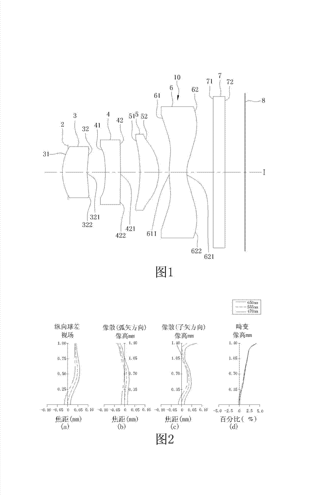
[0093] 1 and 3, the first preferred embodiment of the optical imaging lens 10 of the present invention includes a diaphragm 2, a first lens 3, a second lens 4, and a third lens in sequence from the object side to the image side 5. A fourth lens 6 and a filter 7 . When the light emitted by an object to be photographed enters the optical imaging lens 10, and passes through the aperture 2, the first lens 3, the second lens 4, the third lens 5, the fourth lens 6, and the filter After the light sheet 7, an image will be formed on an imaging plane 8 (Image Plane). The filter 7 is an infrar...


PUM


Abstract

The invention provides an optical imaging lens and an electronic device applying the same. The optical imaging lens sequentially comprises a first lens, a second lens, a third lens and a fourth lens from an object side and an image side; and each lens comprises an object side face facing to the object side and an image side face facing to the image side. The first lens is a lens with a positive refractive index; and the object side face of the first lens is a convex face. The second lens is a lens with a negative refractive index; and the image side face of the second lens is provided with a convex face part located in an area near the circumference. The image side face of the third lens is a convex face. The object side face of the fourth lens is provided with a convex face part located in an area near an optical axis; and the image side face of the fourth lens is provided with a concave face part located in the area near the optical axis, and a convex face part located in the area near the circumference. The electronic device applying the optical imaging lens comprises a shell and an image module comprising the four-sheet optical imaging lens. The electronic device applying the optical imaging lens provided by the invention still has good optical properties when the length of the optical imaging lens is reduced.

Description

technical field [0001] The invention relates to an optical lens, in particular to an optical imaging lens and an electronic device using the lens. Background technique [0002] In recent years, the popularity of portable electronic products such as mobile phones and digital cameras has led to the vigorous development of technologies related to image modules (mainly including optical imaging lenses, module holder units, and sensors). The trend of thinner and lighter cameras also makes the miniaturization of image modules more and more demanding. ) technological progress and size reduction, the length of the optical imaging lens loaded in the image module also needs to be shortened accordingly, but in order to avoid the decline of photographic effect and quality, good optical performance must still be taken into account when shortening the length of the optical imaging lens. How to effectively reduce the system length of the optical lens while still maintaining sufficient opt...

Claims


Application Information

Patent Timeline
Patent Type & Authority Applications(China)
IPC IPC(8): G02B13/18G02B13/00H04N5/225
Inventor 张国文李柏彻骆威谕
Owner GENIUS ELECTRONICS OPTICAL XIAMEN
Why Eureka
Try Eureka