Inclined angle flexible needle robot auxiliary puncture system based on piezoelectric actuation
A robot-assisted, piezoelectric-driven technology, applied in surgical robots, puncture needles, trocars, etc., can solve the problems of difficult movement accuracy, difficult trajectory planning, complex force, etc., and achieves simple structure, small friction torque, easy-to-control effects
- Summary
- Abstract
- Description
- Claims
- Application Information
AI Technical Summary
Problems solved by technology
Method used
Image
Examples
specific Embodiment approach 1
[0010] Specific embodiment one: combine 1 and Figure 4 Describe this embodiment, a robot-assisted puncture system based on a piezoelectric drive with an inclined angle flexible needle in this embodiment includes a needle motor 5, a platform 6, a motor mounting seat 7, a coupling 8, a guide rail 10, and a lead screw head Bearing housing 11, lead screw 12, moving nut 13, slider 14, slider nut connector 15, flexible pin fixing member 16, slider nut connector 17, piezoelectric input connector 18, screw end bearing housing 19 , support piece 21, support sleeve 22, flexible feed needle 23 and bearing support 26, support piece 21, screw end bearing seat 19, lead screw head end bearing seat 11 and motor mounting seat 7 are arranged in sequence from left to right On the platform 6, the needle-feeding motor 5 is arranged on the motor mount 7, and the output shaft of the needle-feeding motor 5 is rotatably arranged on the bearing seat 19 at the tail end of the screw and the bearing seat...
specific Embodiment approach 2
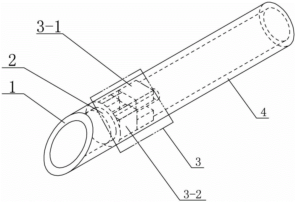
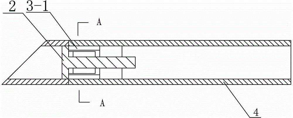
[0013] Specific implementation mode two: combination Figure 1-Figure 3 The present embodiment will be described. The inclination angle of the left end of the needle tip 1 of the present embodiment is 45 degrees. Such arrangement facilitates rapid and accurate penetration into human tissues. Other compositions and connections are the same as in the first embodiment.
specific Embodiment approach 3
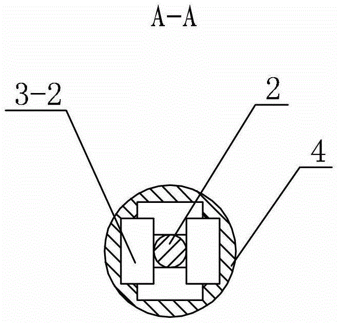
[0014] Specific implementation mode three: combination Figure 1-Figure 3 This embodiment will be described. The connecting rod 2 of this embodiment is an elastic connecting rod. In this way, due to the existence of elastic force and friction coefficient, when the piezoelectric ceramic 3 undergoes a shearing movement, there will be friction between the upper surface of the piezoelectric ceramic 3 and the connecting rod 2 . When the shearing motion is slow, the frictional force is static frictional force. The connecting rod 2 rotates with the upper surfaces of the four piezoelectric ceramics 3 and does not move relative to each other. When the shearing motion is fast, the frictional force Expressed as dynamic friction, the connecting rod 2 does not rotate with the upper surfaces of the four piezoelectric ceramics 3 or rotates slowly, and there is relative motion between each other. When the piezoelectric ceramics 3 move faster in one direction, the other direction When the mov...
PUM
 Abstract
Description
Claims
Application Information
 - R&D
- Intellectual Property
- Life Sciences
- Materials
- Tech Scout
- Unparalleled Data Quality
- Higher Quality Content
- 60% Fewer Hallucinations
Browse by: Latest US Patents, China's latest patents, Technical Efficacy Thesaurus, Application Domain, Technology Topic, Popular Technical Reports.
© 2025 PatSnap. All rights reserved.Legal|Privacy policy|Modern Slavery Act Transparency Statement|Sitemap|About US| Contact US: help@patsnap.com


