Particle beam irradiation system and correction method for charged particle beam

A technology of charged particle beam and irradiation system, applied in the directions of X-ray/γ-ray/particle irradiation therapy, radiotherapy, irradiation device, etc., can solve problems such as unfavorable beam utilization efficiency, beam exhaustion, and reduced irradiation dose consistency. , to achieve the effect of improving beam utilization efficiency

Active Publication Date: 2016-02-24
HITACHI LTD
View PDF4 Cites 0 Cited by
  • Summary
  • Abstract
  • Description
  • Claims
  • Application Information

AI Technical Summary

Problems solved by technology

[0004] If the amount of accumulated charge does not satisfy the irradiation dose per unit, the beam will be exhausted in the middle if the irradiation is performed directly, and the uniformity of the irradiation dose will decrease
Conversely, it is disadvantageous in terms of beam utilization efficiency if the accumulated beam that does not satisfy the irradiation amount of one unit is not used.

Method used


Image

  • Particle beam irradiation system and correction method for charged particle beam
  • Particle beam irradiation system and correction method for charged particle beam
  • Particle beam irradiation system and correction method for charged particle beam

Examples


Embodiment 1

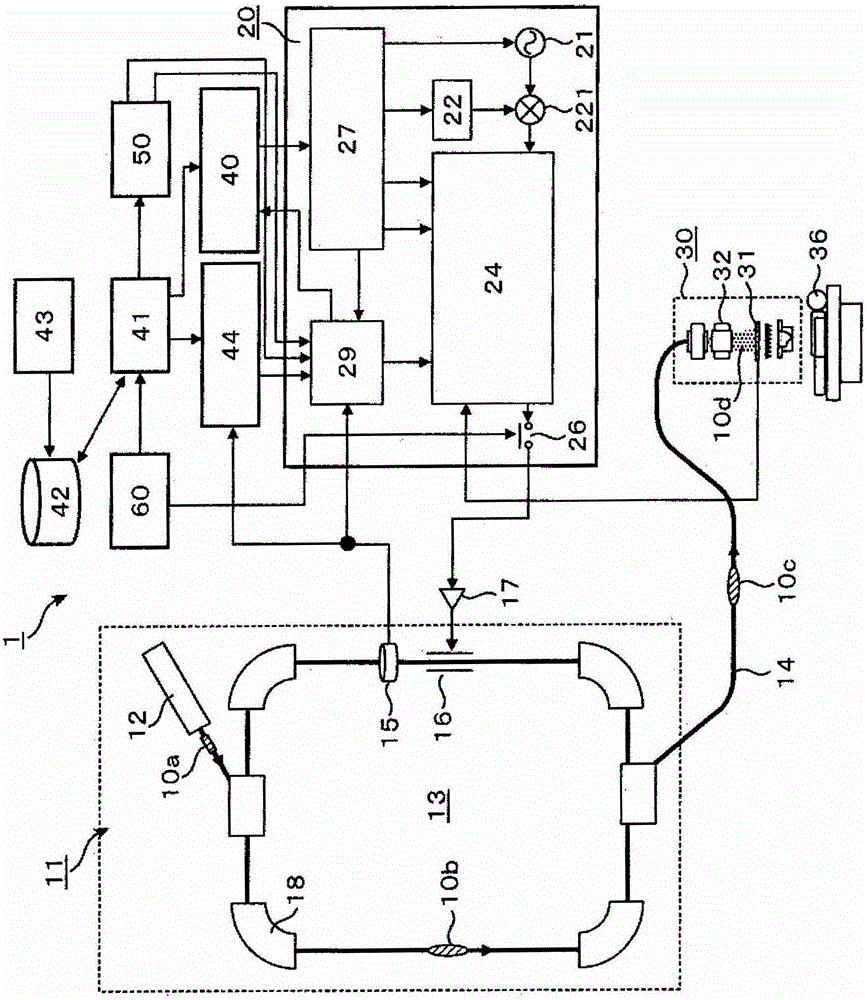
[0046] use figure 1 , figure 2 as well as image 3 A particle beam irradiation system as a preferred embodiment of the present invention will be described. The particle beam irradiation system 1 of the present embodiment is as figure 1 As shown, an ion beam generating device 11, a beam transporting device 14, and an irradiation field forming device (charged particle beam irradiation device, hereinafter referred to as an irradiation device) 30 are provided. The irradiation devices 30 in the room are connected.

[0047] The control system of the above-mentioned particle beam irradiation system 1 includes: an accelerator control device 40 for controlling the ion beam generating device 11 and the beam delivery device 14; a centralized control device 41 for centrally controlling the entire particle beam irradiation system 1; Conditional treatment planning device 43; storage device 42 for storing the information planned by the treatment planning device 43, the control informati...

Embodiment 2

[0107] Shows the second embodiment of the present invention. The device structure of this embodiment is the same as that of the first embodiment, but the target beam current value (I fb ) are corrected in different ways.

[0108] use Figure 9 The beam irradiation control flow will be described. and Figure 6 The difference is that instead of based on the comparative charge (Q comp ) target beam current value (I fb ) of the modified control ( Figure 6 818~820), and the setting is based on the amount of charge irradiated in advance (Q carry ) target beam current value (I fb )'s early correction control ( Figure 9 825-828).

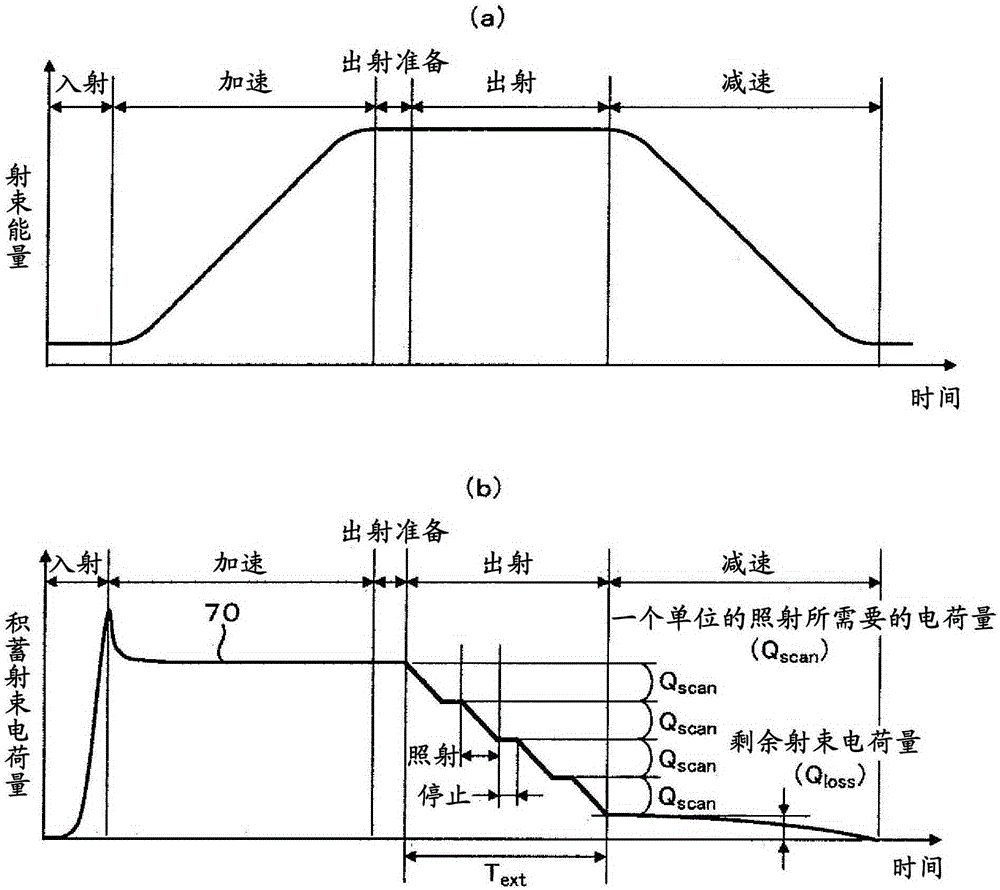
[0109] In the case of the first embodiment, with the exit control time of the synchrotron (T ext ) passes through, the accumulated beam charge (Q meas )reduce. In addition, after becoming the emission control time (T ext ) in the second half of the time, it is considered that the accumulated beam charge (Q meas ) relative to the amount of ch...


PUM


Abstract

PURPOSE: A corpuscular radiation treatment system and a charged particle beam compensation method are provided to increase beam efficiency by not decreasing uniformity of irradiation. CONSTITUTION: A synchrotron(13) accelerates and emits ion beam(10). An irradiator(30) irradiates the ion beam emitted from the synchrotron. An accumulated beam charge measurement unit(15) measures accumulated beam charge in the synchrotron. A target current configuration unit sets up a target beam current value emitted from the synchrotron based on the accumulated beam charge measured in the accumulated beam charge measurement unit. An emitted beam current correction control unit controls beam current based on a target value of the emitted beam current calculated from the target current configuration unit.

Description

technical field [0001] The present invention relates to a particle beam irradiation system and a correction method of a charged particle beam, and particularly relates to a suitable particle beam for a particle beam therapy device suitable for irradiating an affected area with a charged particle beam (ion beam) such as protons or heavy ions to treat cancer An irradiation system and a charged particle beam emitting method. Background technique [0002] As radiation therapy for cancer, particle beam therapy is known in which an ion beam such as protons or heavy ions is irradiated to a patient's cancerous site for treatment. As an ion beam irradiation method, there is a uniform scanning irradiation method as disclosed in Patent Documents 1 to 3 and Non-Patent Documents 1 and 2. [0003] In the uniform scanning irradiation method, in order to maintain the uniformity of the irradiation dose, it is necessary not to exhaust the beam during the irradiation of one unit of a predeter...

Claims


Application Information

Patent Timeline
Patent Type & Authority Patents(China)
IPC IPC(8): A61N5/10
CPCA61N5/10G21K5/04H05H7/001H05H13/04H05H2007/004H05H2277/11
Inventor 西内秀晶藤高伸一郎
Owner HITACHI LTD
Why Eureka
Try Eureka