Hologram recording device

Inactive Publication Date: 2008-08-21
FUJITSU LTD
View PDF4 Cites 4 Cited by
  • Summary
  • Abstract
  • Description
  • Claims
  • Application Information

AI Technical Summary

Benefits of technology

[0007]The present invention has been proposed under the above-described circumstances. It is an object of the present in

Problems solved by technology

The thinning of the beam, however, results in a

Method used


Image

  • Hologram recording device
  • Hologram recording device
  • Hologram recording device

Examples


first embodiment

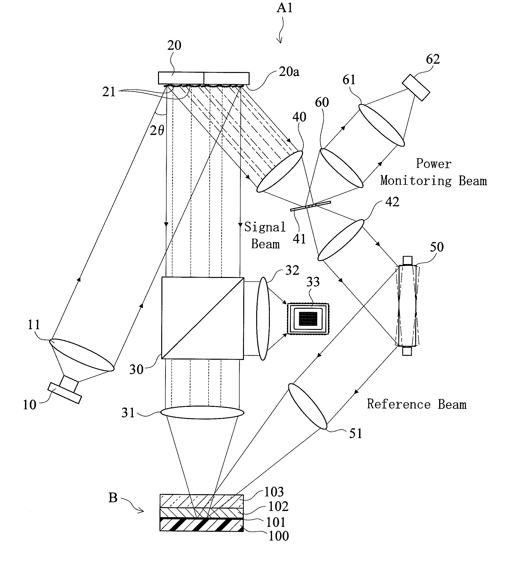
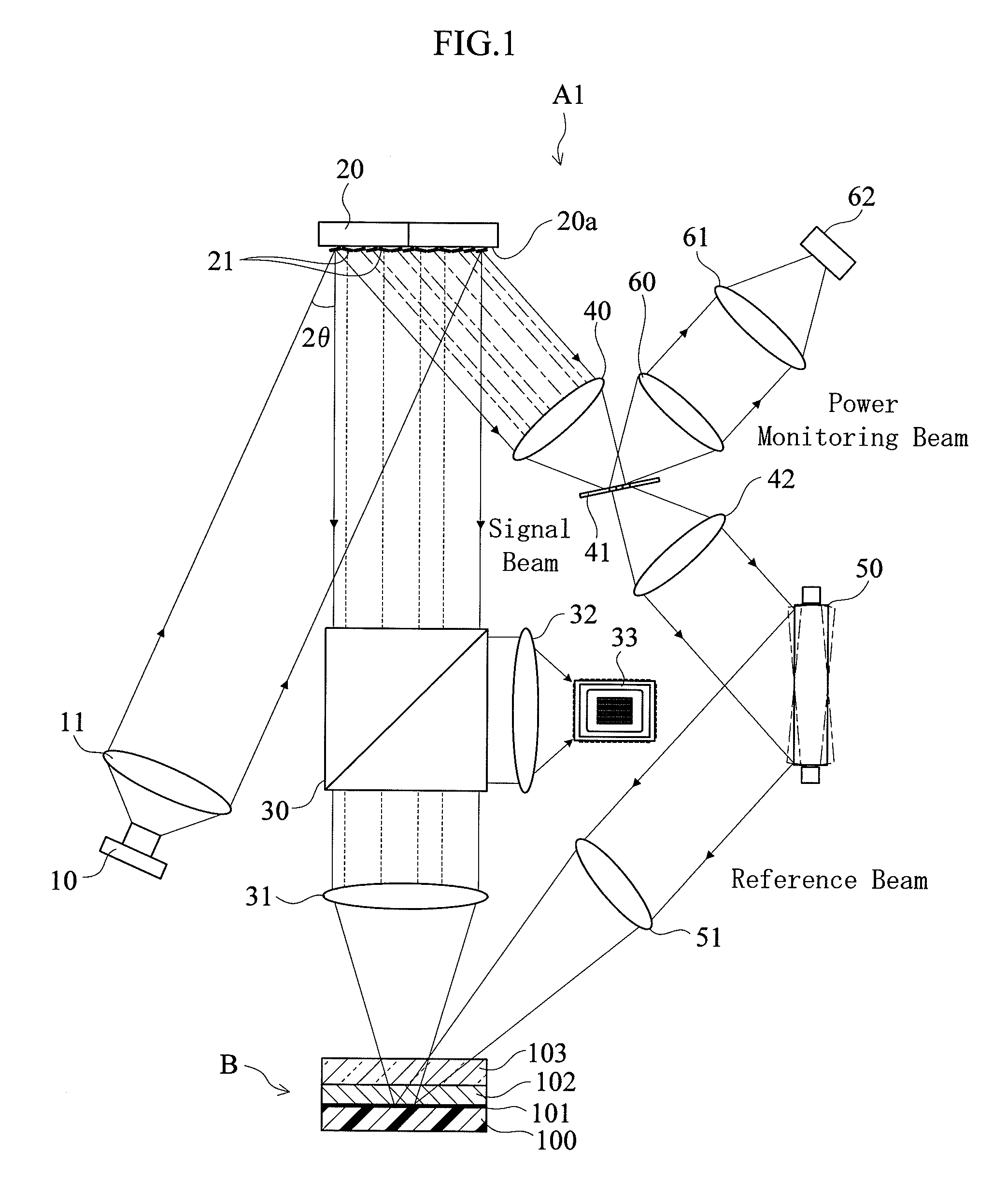
[0029]FIG. 1 through 5 show a hologram recorder according to the present invention.

[0030]As shown in FIG. 1, a hologram recorder A1 is apparatus for recording holograms on a disc-shaped hologram recording medium B (only partially shown in the figure), and reconstructing the recorded holograms. The hologram recorder A1 includes a light source 10, a collimator lens 11, a spatial light modulator 20, a half mirror 30 and an object lens 31 of an optical system for signal / reconstruction beam, a condenser lens 32 of an optical system for reconstruction beam, a reconstruction light sensor 33, a condenser lens 40, an optical filter 41 and a collimator lens 42 for wavefront reshaping, a galvanomirror 50 and an object lens 51 of an optical system for reference beam, relay lenses 60, 61 of a power monitoring optical system, and a power-monitoring light sensor 62. Further, though not shown in the figure, the hologram recorder A1 is provided with a drive mechanism for rotating the hologram record...

third embodiment

[0049]As shown in FIG. 7, a hologram recorder A3 includes an optical filter 41 which is placed in a focal plane of the wavefront reshaping condenser lens 40 and has a pinhole 41. Between the optical filter 41 and a galvanomirror 50, there is disposed a half mirror 43 which, after the beam has passed the pinhole 41C, separates the beam into a reference beam and a power monitoring beam.

[0050]According to the pinhole 41C in the optical filter 41, even the beam which has been discretely thinned by a spatial light modulator 20 is extracted as a low-frequency component beam that has a reshaped wavefront, and this beam is as uniform as the beam before entering the spatial light modulator 20 in terms of beam intensity distribution. After the pinhole 41C, the beam is made into a parallel beam by a collimator lens 42, and then separated into the reference beam and the power monitoring beam by the half mirror 43. The reference beam then reflects on the galvanomirror 50, passes through an obje...

fourth embodiment

[0052]As shown in FIG. 8, a hologram recorder A4 includes a beam splitter 12 disposed between a collimator lens 11 and a spatial light modulator 20. A parallel beam which comes out of the collimator lens 11 is split by the beam splitter 12 in two directions: One beam travels to the spatial light modulator 20 while the other is used as a reference beam.

[0053]The reference beam which has been split by the beam splitter 12 reflects on a reflector plate 13, then on a galvanomirror 50, then passes through an object lens 51 in the reference beam optical system, and then illuminates the hologram recording medium B.

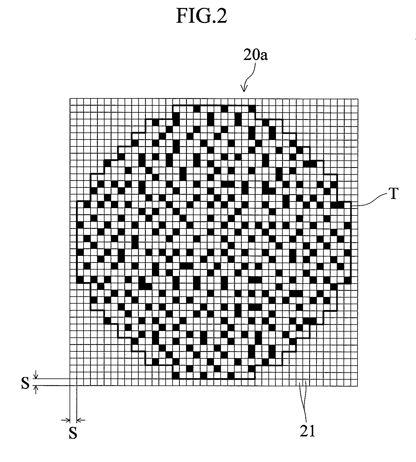
[0054]The beam which comes out of the beam splitter 12 and enters the spatial light modulator 20 has an angle of 2θ with respect to a normal line drawn to the main surface 20a. In the spatial light modulator 20, abeam which is reflected by a beam reflection element 21 at the ON angle +θ becomes a signal beam which travels in a main direction perpendicular to the hologram recordi...


PUM


Abstract

A hologram recorder (A2) includes: a light source (10) for emitting a coherent beam; a spatial light modulator (20) provided with unit areas having a plurality of beam reflection elements (21) to reflect the beam from the light source (10) in a main direction as a signal beam or a cut-off direction; and a signal beam optical system (30, 31) for directing the signal beam to the hologram recording medium B. The recorder (A2) further includes: a wavefront reshaper (40, 41, 42) for condensing the beams thinned out in the cut-off direction by the beam reflection element (21) of the modulator (20), and reshaping the wavefront of the condensed beams; and a reference beam optical system (50, 51) for directing the beam from the reshaper (40, 41, 42) to the recording medium (B) as a reference beam to be shone in an overlapping manner with the signal beam.

Description

[0001]This application is a continuation of International Application No. PCT / JP2005 / 017027, filed Sep. 15, 2005.FIELD OF THE INVENTION[0002]The present invention relates to hologram recorders for recording holograms by using a signal beam and a reference beam shone onto a recording medium in an overlapping manner.BACKGROUND ART[0003]A conventional hologram recorder is disclosed in Patent Document 1 for example. In the hologram recorder, a laser beam from a light source is split by a half mirror in two directions. One of the split beams is modulated by a spatial light modulator which is provided by a liquid-crystal device. The spatial light modulator modulates the beam into a discrete beam which provides a digital (light and dark) pixel pattern in accordance with the information to be recorded. This beam is shone as a signal beam to a hologram recording medium. The other of the beams split by the half mirror is shone as a reference beam so that it will overlap with the signal beam o...

Claims


Application Information

Patent Timeline
IPC IPC(8): G03H1/04G11B7/1381G11B7/1392G11B7/0065
CPCG03H1/04G03H1/0402G03H2222/35G11B7/083G03H2225/24G11B7/0065G03H2222/36G11B7/1392G11B7/1381
Inventor UNO, KAZUSHITEZUKA, KOUICHIYOSHIKAWA, HIROYASUIWAMURA, YASUMASAYAMAKAGE, YUZURU
Owner FUJITSU LTD
Why Eureka
Try Eureka