Thermally-assisted magnetic recording head with plane-emission type light source

a magnetic recording and plane-emission technology, applied in the field of magnetic recording heads, can solve the problems of insufficient laser output power, head cannot write data to the magnetic recording medium, and degradation of the thermal stability of the magnetization,

Active Publication Date: 2012-07-17
TDK CORPARATION
View PDF16 Cites 4 Cited by
  • Summary
  • Abstract
  • Description
  • Claims
  • Application Information

AI Technical Summary

Benefits of technology

[0010]It is therefore an object to provide a thermally-assisted magnetic recording head with a surface-emitting light source, an HGA provided with the head, and a magnetic recording apparatus provided with the HGA, whereby a sufficient light power can be led with a micro light spot to a desired position.
[0014]The parallel beam from the surface-emitting type light source configured by a surface-emitting laser diode is focused by the first diffraction optical element, and the focused beam is collimated by the second diffraction optical element. The collimated beam is incident on the waveguide that is integrally formed with the second diffraction optical element and made of the same material as that of the second diffraction optical element. The optical path of the incident beam of the waveguide is converted by the optical-path direction conversion element and the path-converted beam is transmitted to opposed-to-medium surface. The surface-emitting type light source emits a large spot-sized substantially parallel beam with a spot diameter of 50 μm or more, but it is necessary to decrease the spot diameter so as to effectively apply the beam into the waveguide with a very small diameter of around 0.5 μm. According to the present invention, because the second diffraction optical element for collimation is provided so that the focused beam focused by the first diffraction optical element is collimated by the second diffraction optical element and the collimated beam is incident on the waveguide, occurrence of multi-mode light due to aberration of the focused beam can be prevented and thus the light beam from the surface-emitting type light source can be extremely efficiently guided to the waveguide. Furthermore, since the second diffraction optical element and the waveguide are integrally formed with each other and made of the same material, an efficiency of beam utilization is extremely improved. As a result, the large powered laser beam from the surface-emitting type light source can be extremely efficiently led to a desired position as a very micro spot beam.
[0015]It is preferred that the surface-emitting type light source and the first diffraction optical element are faced to each other through an air space. In this case, preferably, an antireflective film is coated on an incident surface of the first diffraction optical element. This antireflective film preferably includes a film for reducing an intensity of a reflected light beam using optical interference. Because the antireflective film is provided, it is possible to increase largely transmission factor of the first diffraction optical element.
[0017]It is further preferred that at least one of the first diffraction optical element and the second diffraction optical element comprises a Fresnel lens or a binary Fresnel lens. By using Fresnel lens or binary Fresnel lens, it is possible to fabricate these diffraction elements thin resulting the efficiency of the head manufacturing process to improve.

Problems solved by technology

However, the decrease in size of the magnetic micro particles raises a problem of degradation in thermal stability of the magnetization due to the decrease in volume.
As a result, the head cannot write data to the magnetic recording medium when the anisotropic magnetic field of the medium exceeds the upper write field limit.
However, from the beginning, more significant problem to be solved exists in how the beam is to be supplied from a light source to the inside of a head, and specifically, where and how the light source is to be arranged.
In a magnetic recording head using such the VCSEL, an insufficient laser output power is likely to lead to serious problems.
Therefore, it is difficult for the use of the VCSEL to meet such a high output power.
As aforementioned, according to the conventional technique, it was impossible to use a surface-emitting laser diode having a sufficient output light power and also it was impossible to realize leading of a beam spot with a micro diameter from the surface-emitting laser diode to a desired position.

Method used


Image

  • Thermally-assisted magnetic recording head with plane-emission type light source
  • Thermally-assisted magnetic recording head with plane-emission type light source
  • Thermally-assisted magnetic recording head with plane-emission type light source

Examples


Embodiment Construction

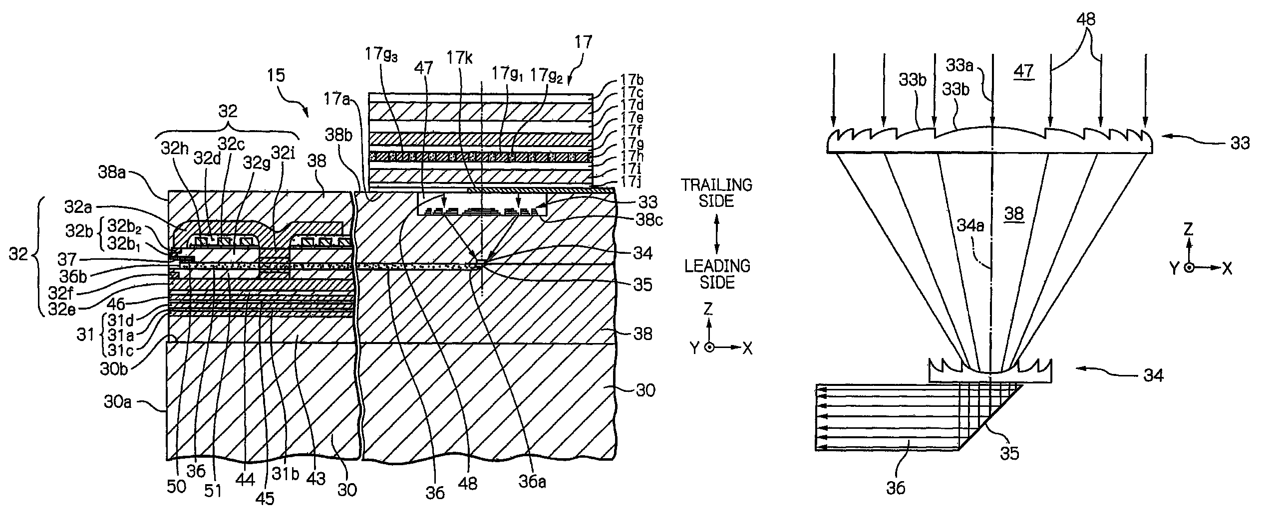
[0037]Hereinafter, the embodiment according to the present invention will be described in detail with reference to these drawings. In the drawings, the same components are indicated using the same reference numerals, respectively. Dimension ratios of components in the drawings are modified to easily understand the embodiment.

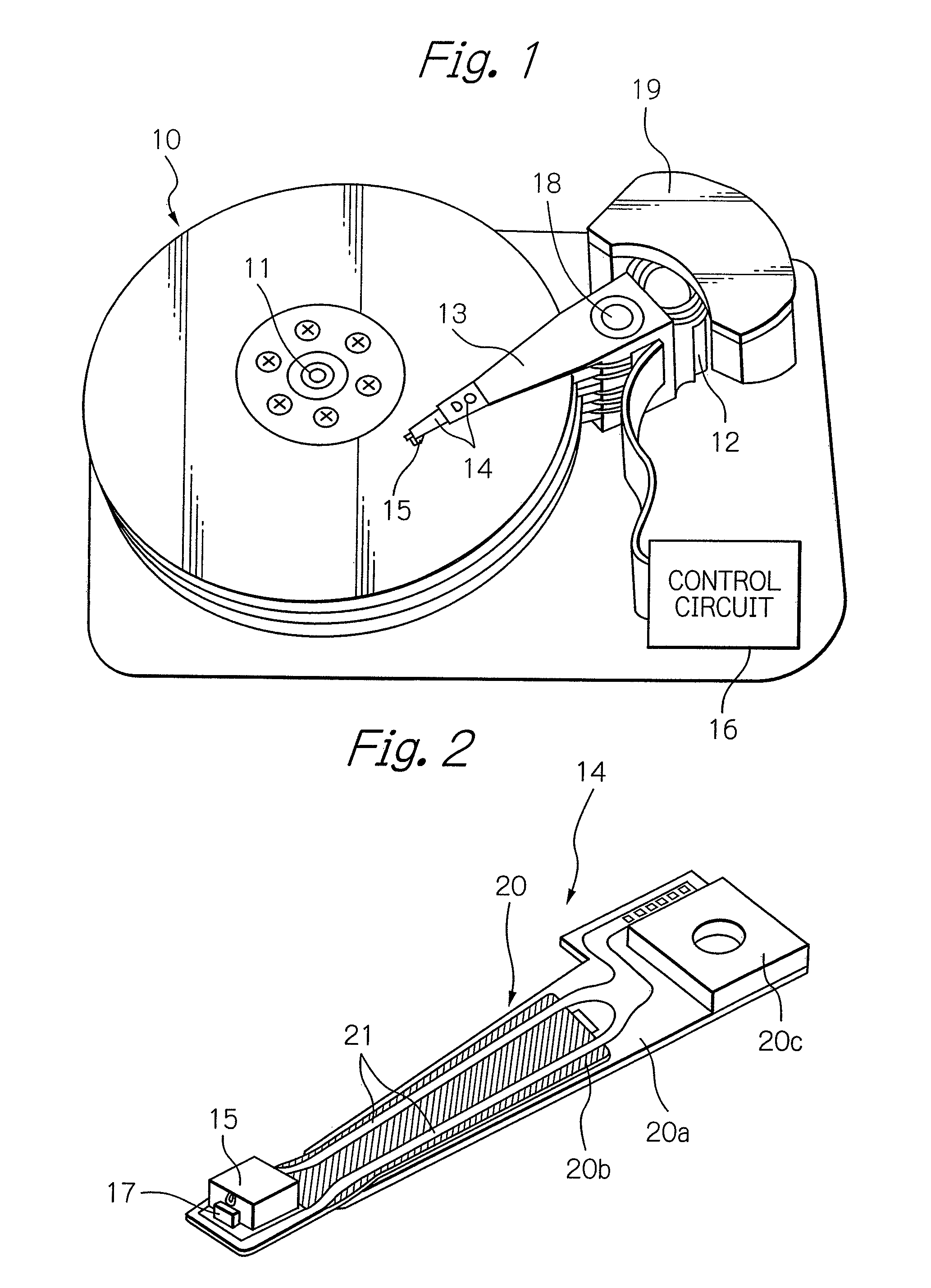
[0038]FIG. 1 schematically illustrates the structure of a major part in an embodiment of a magnetic recording apparatus and an HGA according to the present invention, and FIG. 2 schematically illustrates the structure of the HGA in the embodiment of FIG. 1. In FIG. 2, a face of the HGA opposed to the surface of the magnetic recording medium is indicated as the upper side.

[0039]As shown in these drawings, a magnetic disk drive apparatus as an example of the magnetic recording apparatus includes a plurality of magnetic disks 10 that correspond to magnetic recording media, rotating around a rotational axis of a spindle motor 11, an assembly carriage device 12 provi...


PUM

PropertyMeasurementUnit
output poweraaaaaaaaaa
diameteraaaaaaaaaa
diameteraaaaaaaaaa

Abstract

A thermally-assisted magnetic recording head includes a surface-emitting type light source for emitting substantially collimated beam, a first diffraction optical element for focusing the substantially collimated beam emitted from the surface-emitting type light source, a second diffraction optical element for collimating the light beam focused by the first diffraction optical element, a waveguide integrally formed with the second diffraction optical element and made of the material as that of second diffraction optical element, the light beam collimated by the second diffraction optical element being incident to the waveguide, an optical-path direction conversion element for converting a direction of an optical path of the incident light beam to a propagation direction of the waveguide, the propagation direction being toward an opposed-to-medium surface, and a magnetic pole for generating write field from its end face on the opposed-to-medium surface side.

Description

BACKGROUND OF THE INVENTION[0001]1. Field of the Invention[0002]The present invention relates to a magnetic recording head used for thermally-assisted magnetic recording in which a magnetic recording medium is irradiated with beam from a plane-emission or surface-emitting type light source, thereby anisotropic magnetic field of the medium is lowered, thus data can be written. Further, the present invention relates to a head gimbal assembly (HGA) provided with the head, and to a magnetic recording apparatus provided with the HGA.[0003]2. Description of the Related Art[0004]As the recording density of a magnetic recording apparatus, as represented by a magnetic disk apparatus, becomes higher, further improvement has been required in the performance of a thin-film magnetic head and a magnetic recording medium. Particularly, in the magnetic recording medium, it is necessary to decrease the size of magnetic micro particles that constitute the magnetic recording layer of the medium, and t...

Claims


Application Information

Patent Timeline
Patent Type & Authority Patents(United States)
IPC IPC(8): G11B11/00
CPCG11B5/314G11B5/6088G11B2005/001G11B2005/0021
Inventor CHOU, TSUTOMUKOMURA, EIJISHIMAZAWA, KOJITAKAYAMA, SEIICHI
Owner TDK CORPARATION
Why Eureka
Try Eureka