Round working table driving and sliding base feed driving device

A technology of feed drive and worktable, applied in the direction of drive device, positioning device, feeding device, etc., can solve the problems of large foreign exchange purchase and low processing efficiency.

Inactive Publication Date: 2013-05-08
苏州爱博纳重工装备科技有限公司
View PDF5 Cites 2 Cited by
  • Summary
  • Abstract
  • Description
  • Claims
  • Application Information

AI Technical Summary

Problems solved by technology

At present, only five crank slot milling machines of this kind have been produced in the world. If such a crank slot milling machine is imported, it will cost about 4 to 7 million euros. Due to the huge investment in equipment, the domestic shipbuilding industry still uses other machines. Crank lathes with low processing efficiency are used to process crank arms, and it takes a lot of foreign exchange to buy imported foreign crank lathes

Method used


Image

  • Round working table driving and sliding base feed driving device
  • Round working table driving and sliding base feed driving device
  • Round working table driving and sliding base feed driving device

Examples


Embodiment Construction

[0019] The circular table driving and sliding seat feeding driving device of the present invention will be further described in detail through specific embodiments.

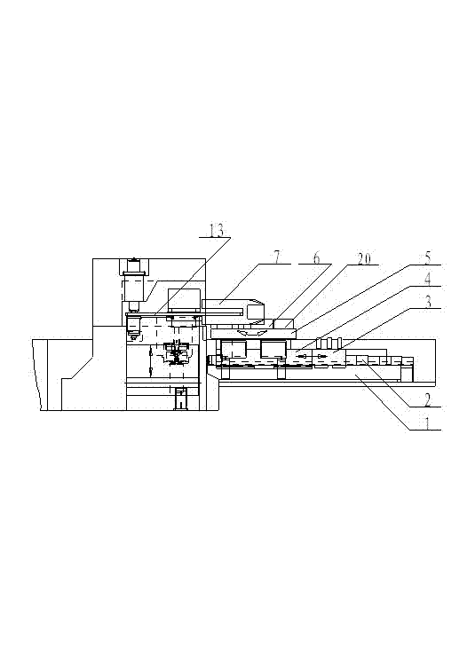
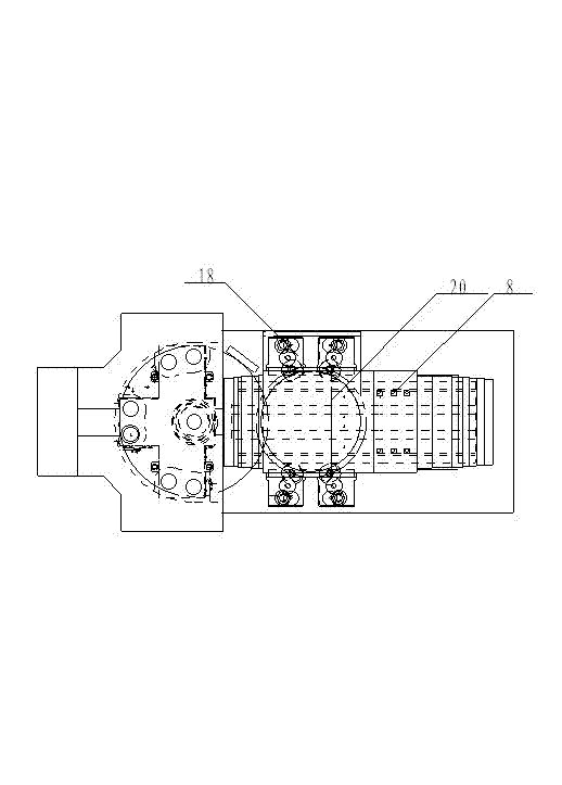
[0020] Such as figure 2 , image 3 , Figure 4 As shown, the overall structural layout design of the CNC crank turning and milling machine is divided into two major working parts: the first working part is the milling circular cutter spindle drive and feed drive combination device; the second working part is the circular worktable workpiece clamping support and sliding seat Feed drive combination.

[0021] The working part of the milling circular cutterhead spindle drive and feed drive combination device, and the work part of the circular worktable workpiece clamping support and slide seat feed drive combination device adopt a series installation combination layout. The workpiece clamping support of the round table and the working part of the sliding seat feed drive combination device are installed at the fro...


PUM


Abstract

The invention relates to a working part of a round working table driving and sliding base feed driving device, which is used for clamping and supporting a workpiece of a round working table of a second working part of a milling machine of a numerical control crank lathe on a crank arm of a crank. The round working table driving and sliding base feed driving device has a main function of driving the round working table for bearing and clamping the workpiece to rotatably feed in the milling machine of the numerical control crank lathe on the crank, and drives a rectangular sliding base to convey the workpiece in a length direction and directly feed. The working part of the round working table driving and sliding base feed driving device, which is designed according to the working characteristics, comprises a lathe body, a sliding base, a transmission box and a driving motor, wherein the sliding base is arranged on the lathe body; the transmission box and the driving motor are used for driving the sliding base to vertically move along an X axis; the round working table for bearing the workpiece, a driving transmission box and the driving motor are further arranged on the sliding base simultaneously; and the driving transmission box and the driving motor are used for driving the round working table to rotatably move around a C shaft.

Description

technical field [0001] The invention relates to a machine tool used in the ship heavy industry for internal milling of crank grooves of crank arms of heavy crankshafts, in particular to a circular worktable drive and a sliding seat feed drive device in the machine tool. Background technique [0002] The crankshaft of a marine low-speed diesel engine in the shipbuilding industry is the core functional component of a marine low-speed diesel engine, which is used to transmit huge torque and propel ships of tens of thousands to hundreds of thousands of tons. The material of the crankshaft is low-carbon alloy steel. Generally, the length of a single crankshaft is 5 to 15 meters and the weight is 30 to 200 tons. A few crankshafts with a weight of more than 300 tons are composed of two crankshafts connected in series. Due to its long length and heavy weight, it is impossible to adopt the assembly structure by adopting the method of integral forging of blanks. It is processed separ...

Claims


Application Information

Patent Timeline
IPC IPC(8): B23C3/06B23Q1/25B23Q1/01B23Q3/06B23Q5/00B23Q5/34B23Q5/10
Inventor 曾金元雷帅王成爽赵冬梅钱伶俊朱国秋张传立黄一平
Owner 苏州爱博纳重工装备科技有限公司
Why Eureka
Try Eureka