Bi-directional positioning clamping fixture

A two-way positioning and clamping technology, which is applied to positioning devices, clamping, manufacturing tools, etc., can solve the problems of waste of resources, inconvenient loading and unloading, and complicated loading and unloading processes, and achieve high positioning accuracy, reduce use costs, and self-locking good performance

Inactive Publication Date: 2013-05-08
CHONGQING ZHIRUIDE TECH
View PDF0 Cites 11 Cited by
  • Summary
  • Abstract
  • Description
  • Claims
  • Application Information

AI Technical Summary

Problems solved by technology

[0004] Although the existing clamping fixture can meet the clamping requirements of the workpiece to a certain extent, in the actual use process, the inventor found that it still has some shortcomings as follows: 1. One-sided pressure is easy to cause the workpiece to be under processing. The displacement in the process is difficult to achieve the accuracy of positioning; 2. The commonly used clamping

Method used


Image

  • Bi-directional positioning clamping fixture

Examples


Example Embodiment

[0013] detailed description

[0014] The technical solution of the present invention will be further described below in conjunction with the drawings and embodiments:

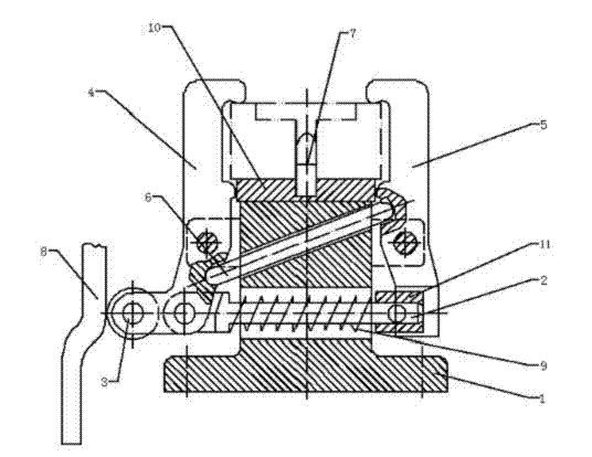
[0015] Such as figure 1 As shown, the present invention provides a bidirectional positioning clamping fixture, comprising a fixture body 1, a left clamping jaw 4 and a right clamping jaw 5 hinged to the fixture body, a push rod 2 fixedly connected with the left clamping jaw 4 A strong spring 9 sleeved on the push rod 2, a sleeve 11 arranged at the transmission end of the push rod 2, a cam 8 as a force applying device, and a linkage pin 6 for driving, characterized in that the clamp body 1 is provided with a horizontal through hole And the inclined through hole, the push rod 2 passes through the horizontal through hole, and its transmission end extends to the rectangular slot corresponding to the lower driving end of the right clamping jaw 5. The linkage pin 6 passes through the inclined through hole and its t...


PUM


Abstract

The invention relates to a clamping fixture and particularly relates to a bi-directional positioning clamping fixture. The fixture comprises a fixture body, a left clamping jaw and a right clamping jaw which are hinged with the fixture body, a push rod fixedly connected with the left clamping jaw, a strong spring sleeved on the push rod, a sleeve arranged at a transmission end of the thrust rod, a cam used as a force application device, and a linkage pin which has the driving function, wherein the fixture body is provided with a horizontal through hole and an inclined through hole; the push rod penetrates through the horizontal through hole, and the transmission end of the push rod extends to a rectangular groove correspondingly formed at a drive end of the lower part of the left clamping jaw; the linkage pin penetrates through the inclined through hole, and two ends of the linkage pin extend to grooves which are correspondingly formed on the left clamping jaw and the right clamping jaw respectively; the drive end of the left clamping jaw is also provided with a roller; the roller is pressed against the cam; and moreover, one end of the strong spring is connected with the push rod, and the other end of the strong spring is connected with the sleeve; By using the bi-directional positioning clamping fixture in the technical scheme, a workpiece can be positioned accurately and is convenient to assemble and disassemble; and the bi-directional positioning clamping fixture is strong in self-locking performance and low in using cost.

Description

technical field [0001] The invention relates to a clamping device, in particular to a bidirectional positioning clamping fixture. Background technique [0002] In the machining and manufacturing industry, the positioning and clamping fixture plays a very important role. It ensures that the workpiece is always in the correct position relative to the machine tool and cutting tool, and ensures the consistency and quality of the workpiece processing. [0003] The traditional clamping fixture achieves the effect of clamping the workpiece by using a combination of levers, springs, pulleys, cams, and handles. The combination of a cam and a lever to press the workpiece is a common clamping fixture. [0004] Although the existing clamping fixture can meet the clamping requirements of the workpiece to a certain extent, in the actual use process, the inventor found that it still has some shortcomings as follows: 1. One-sided pressure is easy to cause the workpiece to be under processin...

Claims


Application Information

Patent Timeline
IPC IPC(8): B23Q3/00
Inventor 严米琪
Owner CHONGQING ZHIRUIDE TECH
Why Eureka
Try Eureka