Knife grinder for grinding formed blade

A knife sharpening device and blade technology, which is applied to other manufacturing equipment/tools, manufacturing tools, etc., can solve the problems of cumbersome procedures, low efficiency, and heavy workload of workers, so as to simplify the processing process, improve work efficiency, and ensure grinding quality effect

Inactive Publication Date: 2013-05-08
台州市奕帆帝门工业设计股份有限公司
View PDF10 Cites 14 Cited by
  • Summary
  • Abstract
  • Description
  • Claims
  • Application Information

AI Technical Summary

Problems solved by technology

The main blade frame in this patent moves along the moving guide rail through the screw rod, and at the same time the blade rotates to realize the grinding of the blade, but in this patent, only round blades can be ground, and the shape of the grinding is single, which cannot meet the requirements of grinding and forming. The requirements f

Method used


Image

  • Knife grinder for grinding formed blade
  • Knife grinder for grinding formed blade
  • Knife grinder for grinding formed blade

Examples


Embodiment 1

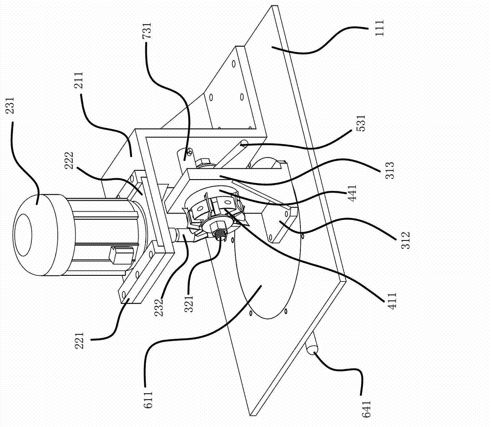
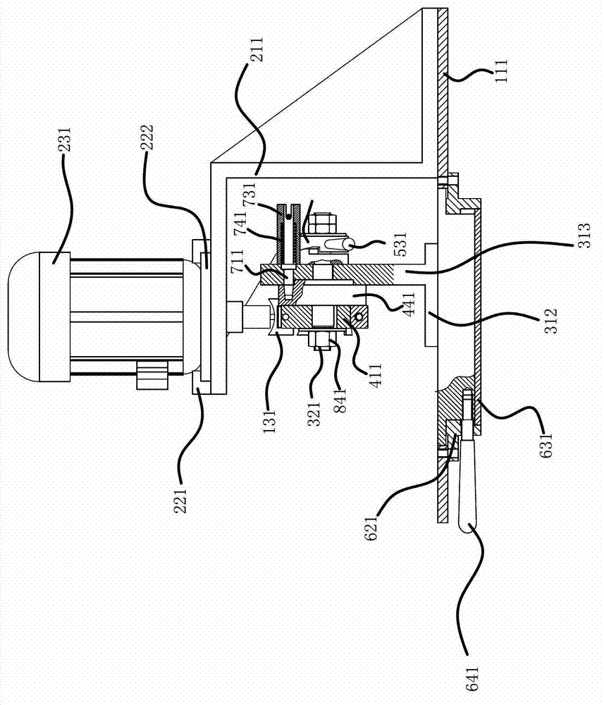
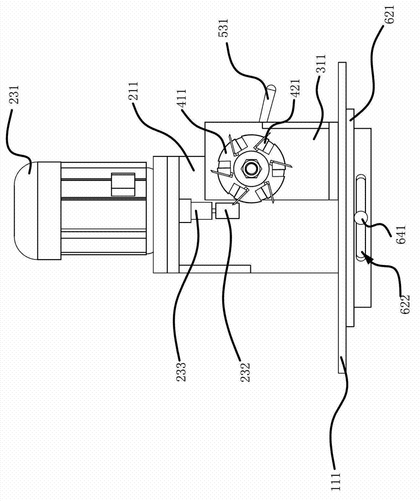
[0028] Such as Figure 1 to Figure 4 As described above, a sharpening device for grinding a shaped blade 131 includes a workbench 111, a motor 231 with a grinding wheel 232 fixed on the motor 231 shaft, and a cutter head 411 for fixing the shaped blade 131. In the first embodiment Forming blade 131 such as Figure 5 As shown, the emery wheel 232 is fixed on the motor shaft through a collet 233, the collet 233 is a common collet available on the market, a motor support 211 is fixed on the workbench 111, and the motor 231 is arranged on the motor support 211 and can be Sliding in the horizontal direction, the workbench 111 is provided with a cutterhead support 311, the cutterhead support 311 can move along the table top of the workbench 111, the cutterhead support 311 passes through a rotating shaft 321, the rotating shaft 321 and the cutterhead support 311 axially Fixed circumferential rotation setting, the cutterhead 411 is fixed on the rotating shaft 321 and is positioned at...

Embodiment 2

[0036] The structure and principle of this embodiment are basically the same as that of Embodiment 1, except that the cutter head support 311 includes a seat plate 312 and a fixed plate 313 vertically fixed on the seat plate 312, and the rotating shaft 321 is vertically installed on the fixed plate 313 Above, the cutter head 411 is located on one side of the fixing plate 313, the fixing mechanism includes a nut and a bearing, the other side of the fixing plate 313 is provided with a positioning groove, the outer ring of the bearing is fixed on the groove wall of the positioning groove, the nut and the bearing The outer end surface of the inner ring of the rotating shaft 321 is fixed, and the rotating shaft 321 is located at the other end of the fixed plate 313 and is provided with a thread. The rotating shaft 321 passes through the inner ring of the bearing and the nut is connected with the thread of the rotating shaft 321. The index plate 441 is fixedly mounted on the rotating...


PUM


Abstract

The invention provides a knife grinder for grinding a formed blade and belongs to the operation technical field. The knife grinder for grinding the formed blade solves the technical problems that the existing knife grinder for grinding a formed blade cannot meet the requirement of multiple cutting edge shapes of grinding the formed blade. The knife grinder for grinding the formed blade comprises an operation platform, a motor which is fixed with a grinding wheel and arranged on a motor shaft and a tool pan which is used for fixing the forming blade. The operation platform is fixed with a motor support, and the motor is arranged on the motor support and moves along the horizontal direction. The operation platform is provided with a tool pan support, the tool pan support moves along a platform surface of the operation platform, and the tool pan is fixed on a rotation shaft and arranged at one side of the tool pan support. The motor shaft of the motor is faced to the tool pan to enable the grinding wheel to contact with the formed blade. A fixing mechanism which fixes the tool pan after the formed blade is opposite to the grinding wheel. The knife grinder for grinding the formed blade has the advantage that grinding of the formed blade with complicated shape is achieved.

Description

technical field [0001] The invention belongs to the technical field of operations, and relates to a knife sharpening device, in particular to a knife sharpening device for grinding shaped blades. Background technique [0002] Many daily necessities such as scrub brush, its handle is usually made of wooden material, and along with the raising of people's living standard, its shape is also more and more diversified. In the production, the handle is formed by turning the shaped blade, and the shape of the wooden handle is derived from the shaped blade, so the shape of the edge of the shaped blade is also diversified. The traditional grinding method of the blade cannot satisfy the shape of the shaped blade. . [0003] In order to solve the above problems, the Chinese patent literature discloses a circular blade grinding machine [CN102672562A], which includes a base, a grinding wheel frame vertical arm, a grinding wheel frame, a blade drive motor, a rotary disc, and a blade fram...

Claims


Application Information

Patent Timeline
IPC IPC(8): B24B3/36
Inventor 牛祥永
Owner 台州市奕帆帝门工业设计股份有限公司
Why Eureka
Try Eureka