Automatic slurry filling device for concrete crack defect with high adhesion strength

A technology of adhesion strength and concrete, which is applied in the direction of building maintenance, construction, building construction, etc., can solve the problems of deep cracks that are difficult to fill, grout leakage, and low efficiency, so as to improve the effect of grouting and improve the stability of installation , Solve the effect of slurry leakage

Active Publication Date: 2018-12-25
GUANGDONG NO 2 HYDROPOWER ENGINEERING COMPANY LTD
View PDF8 Cites 11 Cited by
  • Summary
  • Abstract
  • Description
  • Claims
  • Application Information

AI Technical Summary

Problems solved by technology

The crack defect reinforcement of the prior art has the following deficiencies: First, for cracks in the vertical direction or cracks on the inclined surface, the problem of grout leakage is likely to occur when using the traditional grouting method; When the concrete slurry is injected into the crack in the direction of gravity, the slurry will flow down under the action of gravity, and it is difficult to fill the depth of the crack, resulting in low reinforcement efficiency; second, when the crack is long, only through the concrete itself Leveling, it is difficult to ensure that it can fill the entire crack. At this time, it is necessary to move the position of the grouting pipe to realize the filling of the crack. In the existing technology, the grouting is often completed by manually moving the grouting pipe Third, after the crack is reinforced, there will be a large repair mark between the reinforced area and the non-reinforced area. From the surface, the reinforced area will bulge a little compared to the non-reinforced area, which is Because the reinforced concrete is naturally solidified in the cracks, its surface smoothness is poor; Fourth, when actually reinforcing, it is usually necessary to install a bracket to fix the position of the grouting pipe, because it is for repairing vertical cracks or oblique Cracks on the drape; in the prior art, the grouting pipe is usually fastened by riveting or manual holding. Although the riveting method has a better fastening effect and saves labor, this method is to destroy the wall or plate. achieved at the expense of the body

Method used


Image

  • Automatic slurry filling device for concrete crack defect with high adhesion strength
  • Automatic slurry filling device for concrete crack defect with high adhesion strength
  • Automatic slurry filling device for concrete crack defect with high adhesion strength

Examples


Embodiment 1

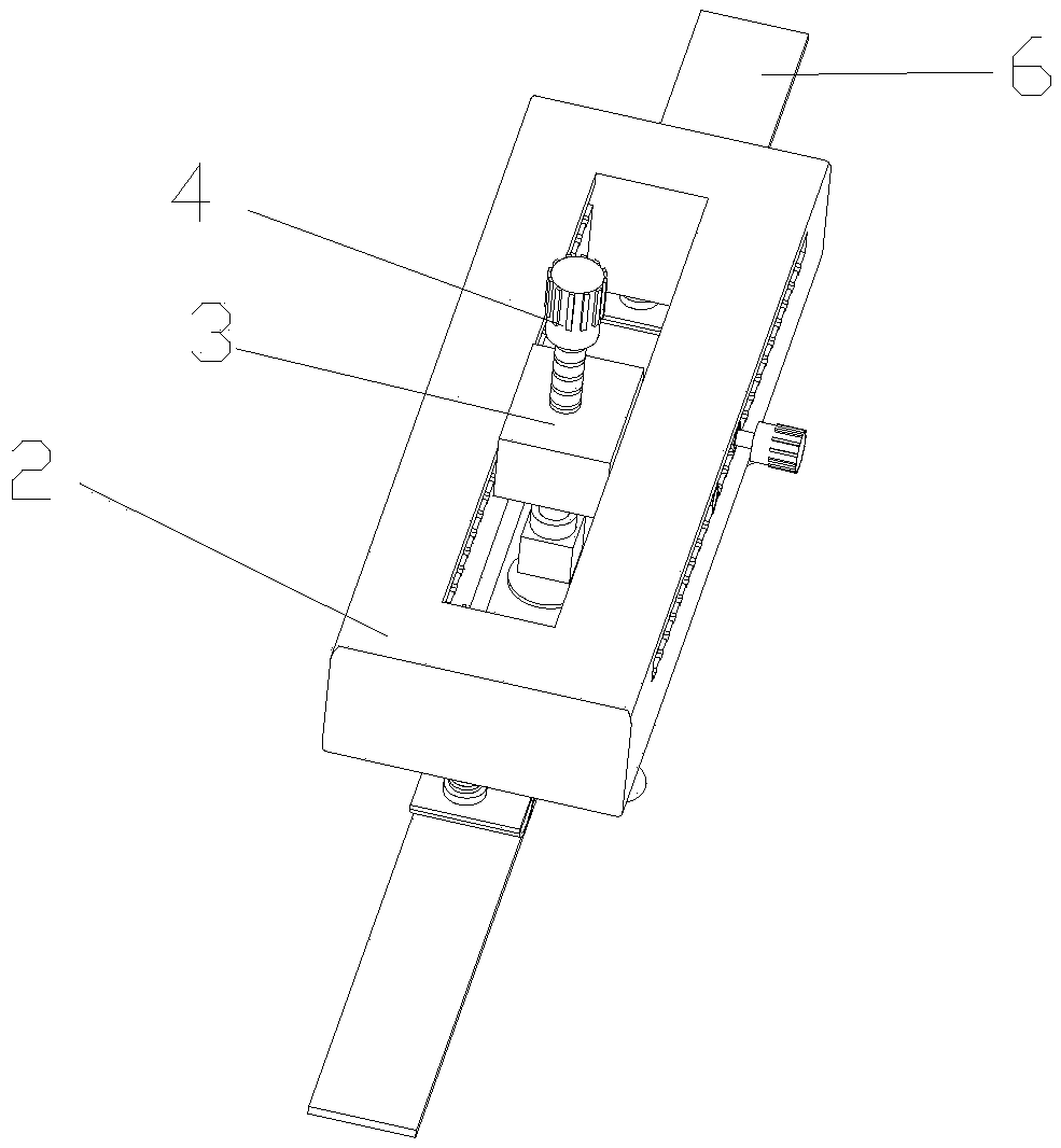
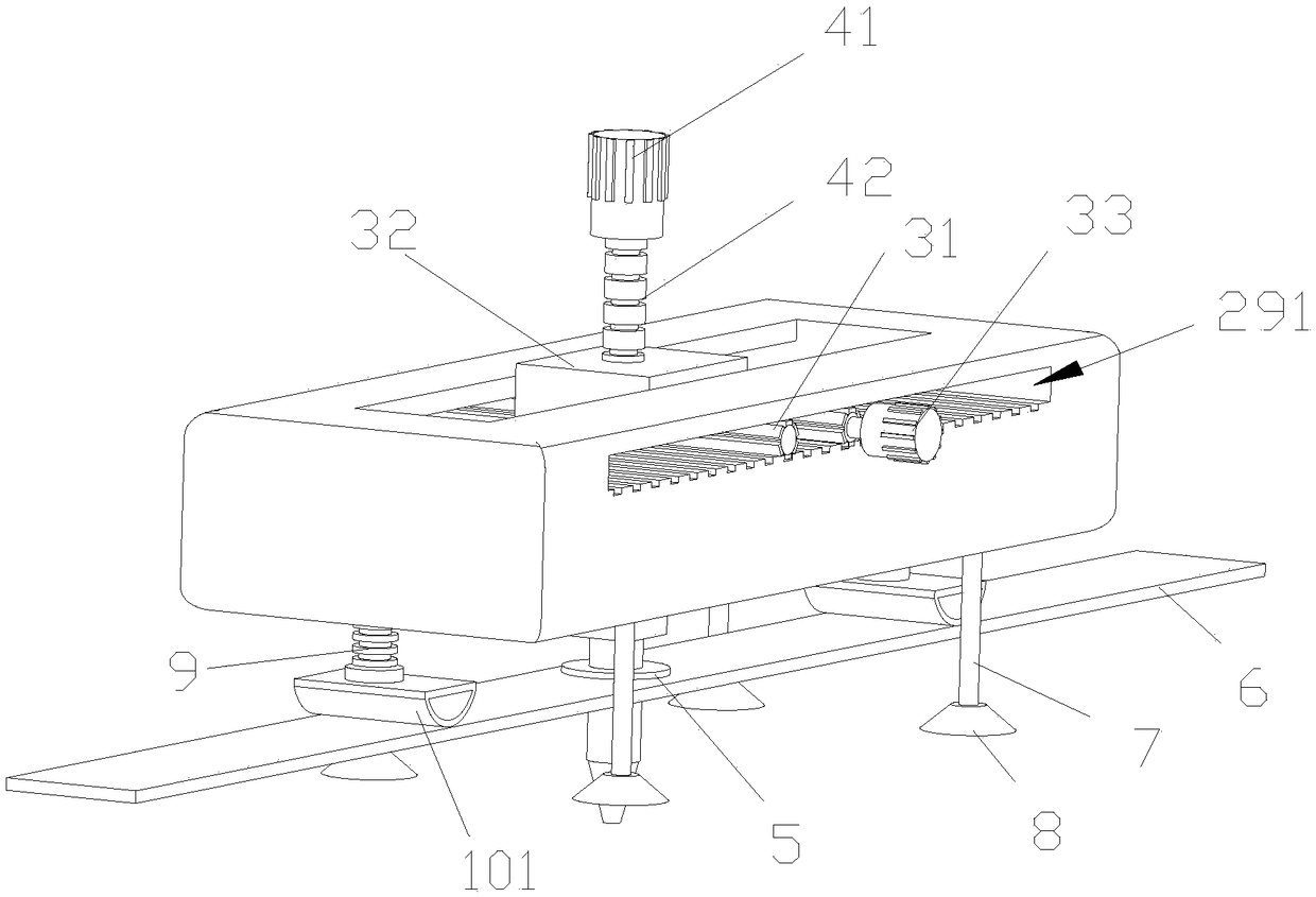
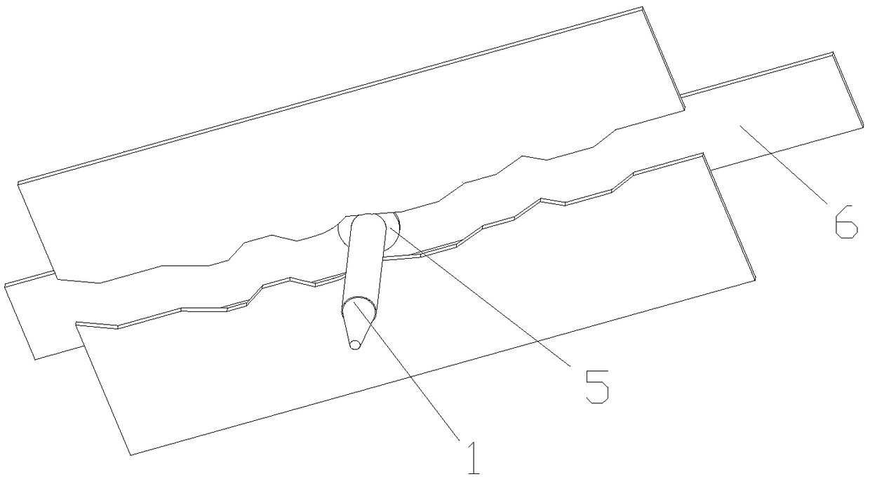
[0043] Such as Figure 1-3 As shown, the present invention discloses an automatic grouting device for concrete crack defects with high adhesion strength, which includes a grouting pipe 1 through which concrete grout is injected into concrete cracks. It also includes a frame 2, an electric sliding part 3, an electric lifting part 4, a rubber sleeve 5, a brickwork knife 6, a first support rod 7, a first suction cup 8, a second support rod 9, and a conflicting part 101. The electric sliding part 3 is slidingly matched with the frame 2, the electric lifting part 4 is set on the electric sliding part 3, the lifting end of the electric lifting part 4 is connected with the grout filling pipe 1, and the brick knife 6 is set on the grout filling pipe through the rubber sleeve 5 1 periphery. One end of the first support rod 7 and one end of the second support rod 9 are all arranged on the frame 2, wherein, the other end of the first support rod 7 can extend toward the position directio...

Embodiment 2

[0047] Such as Figure 4 As shown, the difference between this embodiment and the above-mentioned embodiments is that the first suction cup 8 is provided with an air suction port 81, and a circle of pressing structure 82 is extended on the edge of the first suction cup 8, and the first support rod 7 is also slidably fitted with a The pressing piece 83 can be pressed against the pressing structure 82 .

[0048]If the concrete wall or board surface is relatively rough or the frame 2 has a large self-weight, it may be difficult to generate sufficient suction force only by manually pressing the first suction cup 8 on the concrete wall or board surface. At this time, By opening an air suction port 81 on the first suction cup 8, the excess air in the first suction cup 8 is further sucked out, and the vacuum degree of the first suction cup 8 is further increased to further increase the suction force. Moreover, by pressing down the pressing member 83 to the pressing structure 82 at t...

Embodiment 3

[0050] Such as Figure 5-7 As shown, the difference between this embodiment and the above-mentioned embodiments is that a first supporting telescopic member 21 is provided at the end of the frame 2, and the first supporting telescopic member 21 includes a first fixed hollow tube 211, at least one first movable Hollow tube 212, the size of the section of each first movable hollow tube 212 is not the same, the first movable hollow tube 212 with smaller cross-sectional size can be sleeved on the first movable hollow tube 212 with larger cross-sectional size Among the hollow parts, the first hollow tube with the largest cross-sectional size can be sleeved in the hollow part of the first fixed hollow tube 211 . In the first fixed hollow tube 211 and the first movable hollow tube 212, there are mounting threaded holes (not shown in the figure), the mounting threaded holes of the first fixed hollow tube 211, the first movable hollow tubes The mounting threaded holes in 212 correspon...


PUM


Abstract

The invention discloses an automatic slurry filling device for a concrete crack defect with high adhesion strength, which comprises a slurry filling pipe, wherein the concrete slurry is injected intothe concrete crack through the slurry filling pipe; and also comprises a machine frame, an electric sliding element, an electric lifting element, a rubber sleeve, a trowel, a first supporting rod, a first sucking disc, a second supporting rod and a abutted element; the electric sliding element is in sliding fit with the machine frame, the electric lifting element is arranged on the electric sliding element, the lifting end of the electric lifting element is connected with the slurry filling pipe, and the trowel is sleeved at the periphery of the slurry filling pipe through the rubber sleeve. The first sucking disc is arranged on the end part of the first supporting rod; the connecting end of the abutted element is slidably mounted on the end part of the second supporting rod, and the abutted end of the abutted element can be contacted with the trowel. The device has the advantages that the crack can be fully filled, the slurry leakage condition is reduced, the flatness of the surface after filling the slurry is high, the slurry filling pipe can achieve sliding and grouting in the crack, and the installation stability of a bracket is high, no damage is caused on a wall body or the adhesion strength of a plate body is high.

Description

technical field [0001] The invention relates to the technical field of concrete reinforcement, in particular to a concrete crack defect automatic grouting device with high adhesion strength. Background technique [0002] Concrete pouring refers to the process of pouring concrete into the mold until it is plasticized. In civil engineering, concrete and other materials are put into the mold to make a predetermined shape. Usually, concrete defects include the following situations. First, the interior of the concrete has voids and voids, which are commonly known as "two skins"; The surface of the concrete is not cleaned properly, and the concrete surface is stuck when the formwork is removed; or, the formwork release agent is not evenly applied, and some parts are missing or invalid, and the concrete surface and the formwork are bonded to cause pockmarks; third, cracks and cracks appear on the concrete surface The problem. The general mechanism of cracks is generally believed ...

Claims


Application Information

Patent Timeline
Patent Type & Authority Applications(China)
IPC IPC(8): E04G23/02
CPCE04G23/0211
Inventor 谢祥明乔晓锋赵雅玲姚楚康邱晓艳
Owner GUANGDONG NO 2 HYDROPOWER ENGINEERING COMPANY LTD
Why Eureka
Try Eureka