Method and apparatus for centering lens aligner

A centering device and lens technology, which is applied to the grinding drive device, the components of the grinding machine, the control of the workpiece feed movement, etc. and other problems, to achieve the effect of high centering accuracy

Active Publication Date: 2013-05-08
NAKAMURATOME SEIMITSU IND
View PDF8 Cites 7 Cited by
  • Summary
  • Abstract
  • Description
  • Claims
  • Application Information

AI Technical Summary

Problems solved by technology

[0005] But when Figure 11 In the conventional means shown, there is such a problem that due to contact measurement by a dial gauge, etc., when the measuring end of the dial gauge abuts against the lens, the lens will be damaged, and since the lens is pushed by the abrasive tool, the lens will be damaged. , will also damage the

Method used


Image

  • Method and apparatus for centering lens aligner
  • Method and apparatus for centering lens aligner
  • Method and apparatus for centering lens aligner

Examples


Embodiment Construction

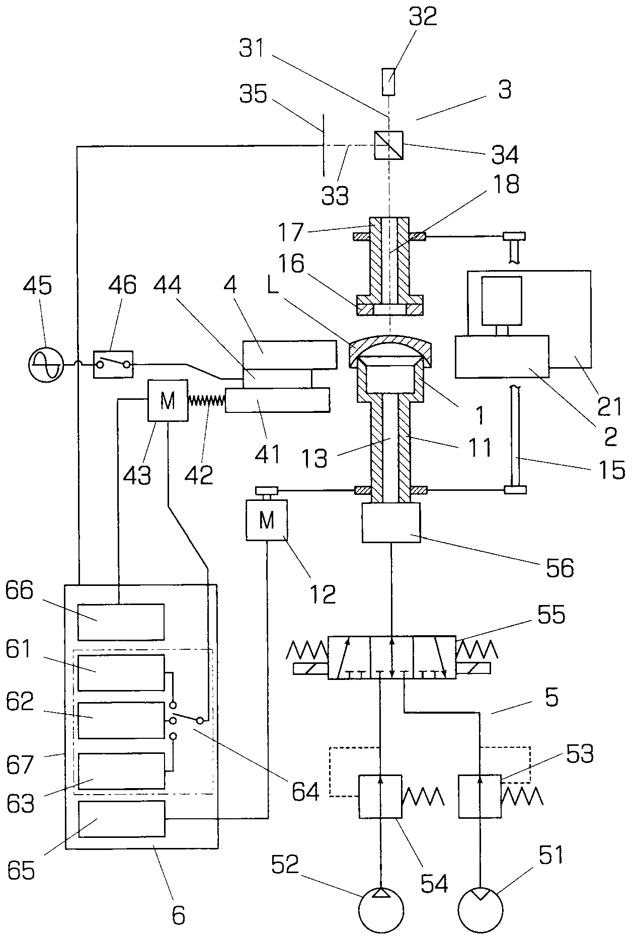
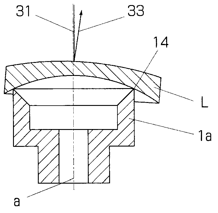
[0030] Hereinafter, embodiments of the invention will be described with reference to examples shown in the drawings. The aligning machine of the illustrated embodiment has: the main shaft 11, which is equipped with an upward cup-shaped cage 1 (corresponding to Figure 10 , 11The component of the cage 1a in the existing structure); the upper shaft 17, which is equipped with an annular pressing pad 16 opposite to the cage 1 at the lower end; The outer periphery of the lens L held by clamping is processed. The main shaft 11 and the upper shaft 17 are arranged on the main shaft axis a in the vertical direction, and are synchronously driven by the main shaft motor 12 and the connecting shaft 15 that rotatably connects the main shaft 11 and the upper shaft 17 . Therefore, the cage 1 and the pad 16 rotate synchronously around the axis a. The upper shaft 17 can be raised and lowered by an elevating device not shown, and the lens L is loaded on the holder 1 in the state where the upp...


PUM


Abstract

A method and an apparatus for centering lens aligner are disclosed. Small lens of the Z value can be accurately centered without causing damages to the lens. The apparatus is provided with a optical measurement device for receiving reflected light or transmission light of light beams projected from the surface of the lens facing a holding frame and outputting photic positions; a push rod arranged independently from a spinning grinding apparatus for processing the periphery of the lens; and a conveying apparatus enabling the push rod to move towards the axis of the holding frame. According to the measurement value of the optical measurement device, the eccentric direction of the lens is made to face the direction of the push rod so as to keep the holding frame rotating, and the push rod is made to move forwards towards the holding frame.

Description

technical field [0001] The present invention relates to the centering of a lens aligning machine that processes the outer periphery of the lens based on the optical axis of the lens, that is, to make the optical axis of the lens placed on the holder holding the lens coincide with the axis or rotation center of the holder Methods and devices. Background technique [0002] After the spherical surface of the front and back of the lens is processed, the outer circumference of the lens is processed based on the optical axis determined by the processed spherical surface. A device that processes the outer periphery of a lens based on the optical axis is called an aligner. A general aligning machine is equipped with: a holder that rotates while holding the lens; a rotating grinder that approaches / distances toward the outer periphery of the lens held by the holder; and an NC controller that controls the approaching / distance of the rotating grinder. Move position away from direction...

Claims


Application Information

Patent Timeline
IPC IPC(8): B24B13/005
CPCB24B9/144B24B41/061B24B47/225B24B49/12
Inventor 山中喜彦
Owner NAKAMURATOME SEIMITSU IND
Why Eureka
Try Eureka