Modular combined-type tower crane attached bar with extensive stepless adjustment-type length

A combined tower crane and stepless adjustment technology, which is applied to cranes and other directions, can solve the problems that the length of the attachment rod cannot meet the on-site installation requirements, the use of tower crane attachment devices is large, and the tower crane attachment devices are not the same. The effects of environmental protection, manpower saving and novel structure

Inactive Publication Date: 2014-07-30
TANGSHAN CONSTR GRP
View PDF4 Cites 0 Cited by
  • Summary
  • Abstract
  • Description
  • Claims
  • Application Information

AI Technical Summary

Problems solved by technology

[0002] In high-rise construction, tower crane attachment devices are used in large quantities, and such problems often occur: First, the standard attachment devices provided by tower crane manufacturers rarely fully meet the conditions of attachment center distance and attachment point distance in actual use , generally cannot be used directly; secondly, due to the constraints of basement building structure and building environment and other factors, the center distance and attachment point distance of the tower crane attachment device are often different in different construction projects, so the length of the attachment rod needs to be adjusted. The third is that when actually measuring the distance between the attachment center and the attachment point, measurement errors often occur. Because the adjustment distance of the original attachment rod is relatively small, generally about ±125mm, the length of the prepared attachment rod often cannot meet the site requirements. Installation requirements, sometimes rework phenomenon
The above technologies have not given specific guidance on how to make the structural size of each part of the attachment rod small, convenient for transportation, and improve the stress conditions of the attachment rod itself, the attachment point and the tower body at the attachment point, so as to make the work safer and more reliable.

Method used


Image

  • Modular combined-type tower crane attached bar with extensive stepless adjustment-type length
  • Modular combined-type tower crane attached bar with extensive stepless adjustment-type length
  • Modular combined-type tower crane attached bar with extensive stepless adjustment-type length

Examples


Embodiment Construction

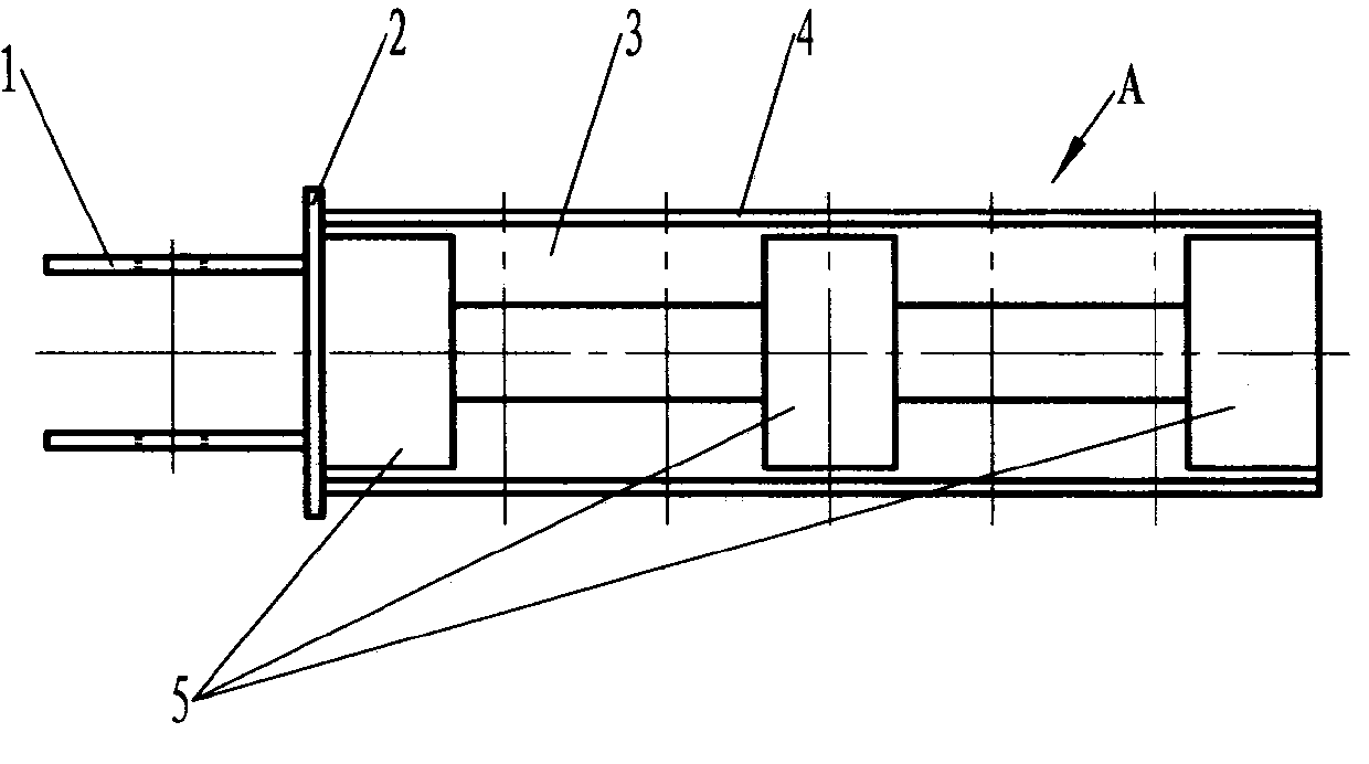
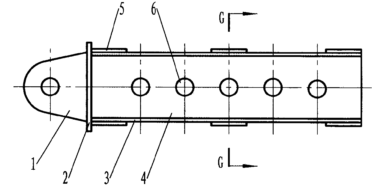
[0041] Such as figure 1 , figure 2 , image 3 , Figure 4 , Figure 5 , Figure 6 , Figure 7 , Figure 8 , Figure 9 , Figure 10 , Figure 11 , Figure 12 As shown, the first embodiment of the present invention has an upper connector E connected to the wall embedded parts, a lower connector E' connected to the ring beam of the tower body, and the lower connector E' through the second pin F 2 Hinged lead screw adjustment device E", through the third pin shaft F 3 The club head A hinged with the connecting piece E, the club tail B connected (fixed connection) with the lead screw adjustment device E″, the first shaft C (and the second shaft D). In this way, the club head A is connected through the upper The part E is connected with the embedded part of the wall, and the rod tail B is connected with the ring beam of the tower body through the screw adjusting device E″ and the lower connecting part E′. A first shaft C or a combination of two first shafts C and one se...


PUM


Abstract

A modularized combined tower crane attachment rod with a large length and stepless adjustment, which has an upper connector, a lower connector, a screw adjustment device, a rod head, a rod tail, a first rod body, and a second rod body. A first shaft or a combination of two first shafts and one second shaft is provided between the club head and the club tail. When a first shaft is provided between the club head and the club tail, the club head and the club tail are respectively inserted into the installation holes at both ends of the first shaft, and are connected together by a first pin shaft. When there is a combination of two first shafts and one second shaft between the club head and the club tail, the two ends of the second shafts are respectively inserted into the mounting holes at one ends of the two first shafts, each through The two fourth pin shafts are connected together, and a rod head and a rod tail are respectively inserted into the mounting holes at the other ends of the two first shafts, and each is connected together by a first pin shaft. It is simple to connect, improves the force condition of the attachment rod itself, the attachment point and the attachment tower body, and makes the work safer and more reliable.

Description

technical field [0001] The invention relates to a tower crane attachment device, which belongs to the tower crane attachment device used in the field of building construction, in particular to a large-range stepless adjustable modularized combined tower crane attachment rod. Background technique [0002] In high-rise construction, tower crane attachment devices are used in large quantities, and such problems often occur: First, the standard attachment devices provided by tower crane manufacturers rarely fully meet the conditions of attachment center distance and attachment point distance in actual use , generally cannot be used directly; secondly, due to the constraints of basement building structure and building environment and other factors, the center distance and attachment point distance of the tower crane attachment device are often different in different construction projects, so the length of the attachment rod needs to be adjusted. The third is that when actually me...

Claims


Application Information

Patent Timeline
Patent Type & Authority Patents(China)
IPC IPC(8): B66C23/78
Inventor 姚振平周建国程启国展翔贺俭赵磊李淑君孙斌张博
Owner TANGSHAN CONSTR GRP
Why Eureka
Try Eureka