Eureka AIR delivers breakthrough ideas for toughest innovation challenges, trusted by R&D personnel around the world.

Manufacturing and machining machine and machining method for aluminum alloy burglary-resisting window

A technology for processing machinery and anti-theft windows, which is applied in metal processing, metal processing equipment, manufacturing tools, etc., and can solve the problems of low work efficiency and inability to automatically clamp and separate individual rods.

Inactive Publication Date: 2021-07-23
苏永碧
View PDF5 Cites 0 Cited by
  • Summary
  • Abstract
  • Description
  • Claims
  • Application Information

AI Technical Summary

Problems solved by technology

[0004] (1) When the existing aluminum alloy anti-theft window installation device is assembling the aluminum alloy anti-theft window, it is impossible to adjust the equal intervals of multiple rods synchronously when installing multiple rods in batches, so the work efficiency is low and the use is limited. limitation;
[0005] (2) When the existing aluminum alloy anti-theft window installation device performs batch synchronous installation of multiple rods, it cannot synchronize and fix multiple rods, so the work intensity is increased, which is time-consuming and laborious;
[0006] (3) The existing aluminum alloy anti-theft window installation device cannot automatically clamp and disengage a single rod before synchronously fixing multiple rods on the aluminum alloy window, so it is not convenient for the entire batch assembly operation

Method used


Image

  • Manufacturing and machining machine and machining method for aluminum alloy burglary-resisting window
  • Manufacturing and machining machine and machining method for aluminum alloy burglary-resisting window
  • Manufacturing and machining machine and machining method for aluminum alloy burglary-resisting window

Examples


Embodiment Construction

[0039] The embodiments of the present invention will be described in detail below with reference to the accompanying drawings, but the present invention can be implemented in many different ways defined and covered by the claims.

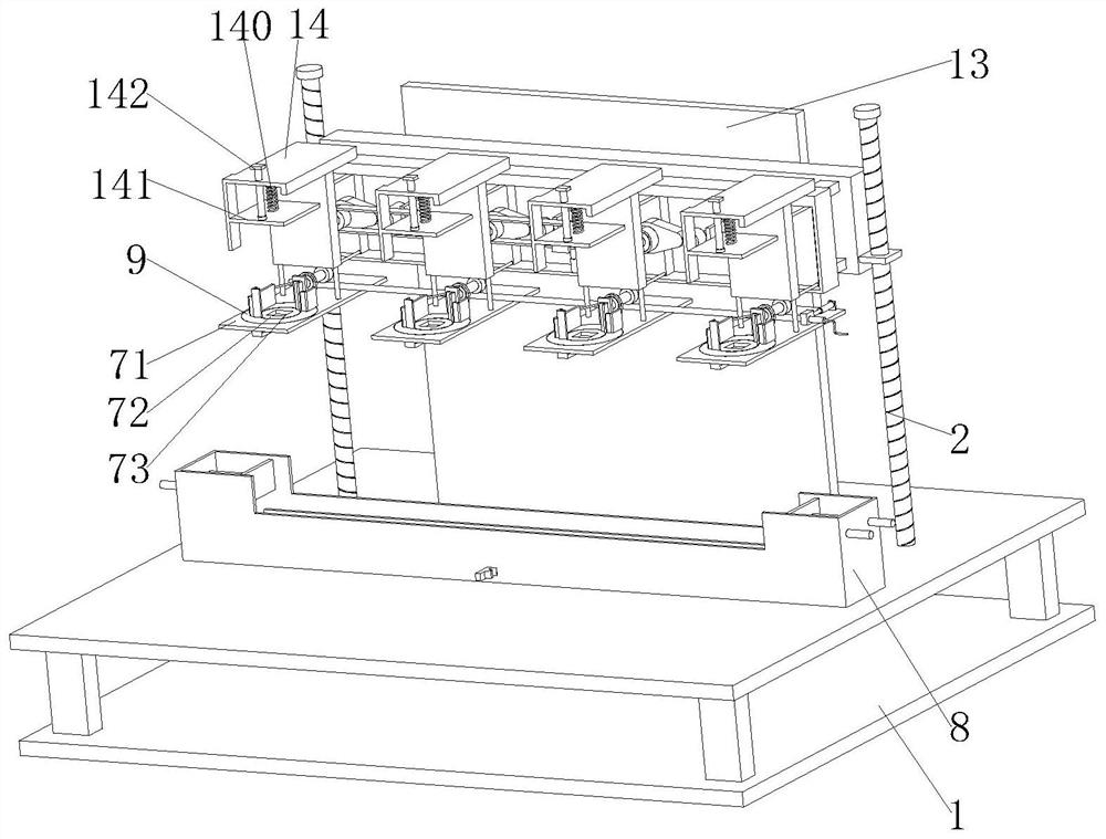
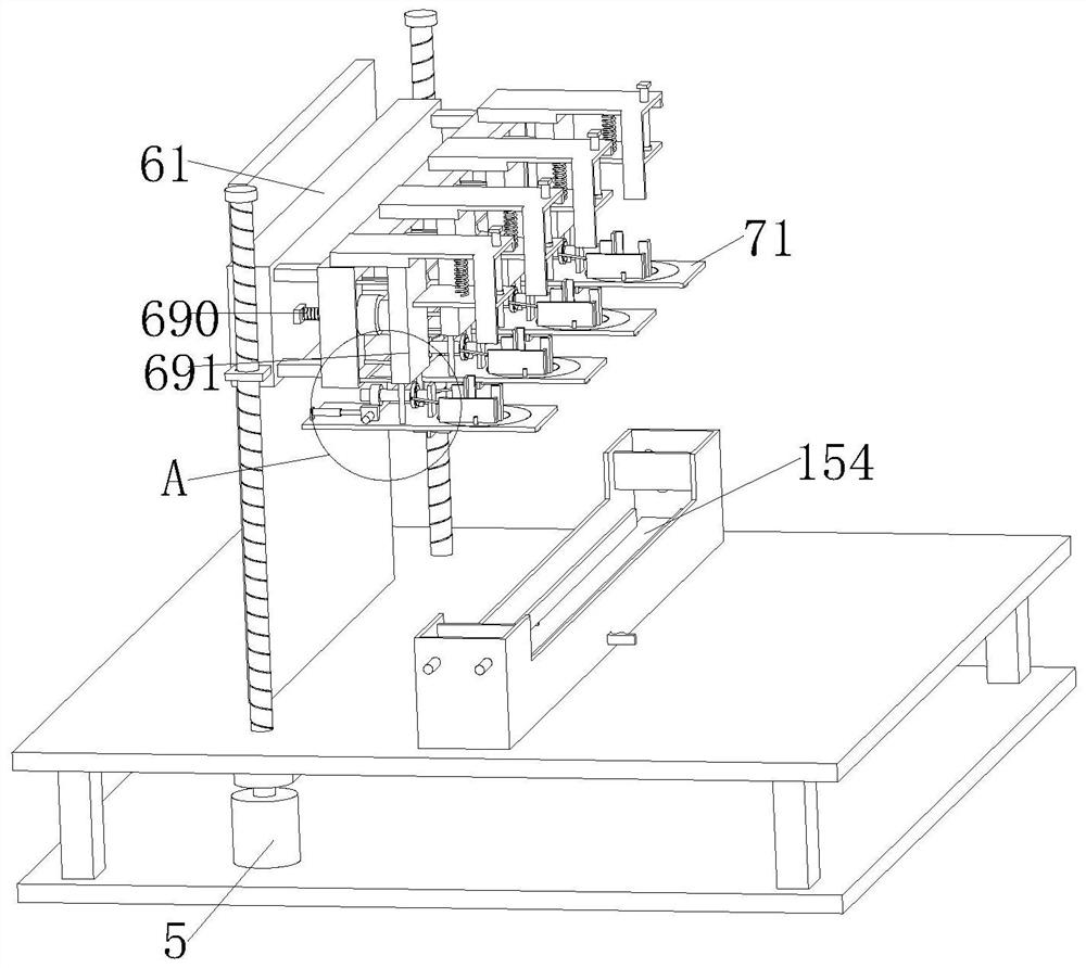
[0040] Such as Figure 1 to Figure 11 As shown, an aluminum alloy anti-theft window manufacturing and processing machine includes a support frame 1, a lifting screw 2, a pulley 3, a belt 4, a lifting motor 5, an adjustment device 6, a fixing device 7 and a placement frame 8. The support frame 1 The upper part of the inner cavity is symmetrically installed with a lifting screw 2, and the lower end of the lifting screw 2 is fixed with a pulley 3, and a belt 4 is arranged between the pulleys 3, and the left side of the lower surface of the inner cavity of the support frame 1 is fixed with a lifting motor through a motor plate 5. The output end of the lifting motor 5 is fixedly connected with the lifting screw 2 on the left side. The lifting screw 2 on ...


PUM


Abstract

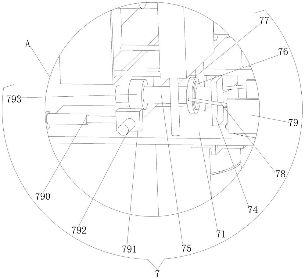
The invention relates to a manufacturing and machining machine and a machining method for an aluminum alloy burglary-resisting window. The manufacturing and machining machine for the aluminum alloy burglary-resisting window comprises a supporting frame, a lifting screw rod, a belt wheel, a belt, a lifting motor, an adjusting device, a fixing device and a placing frame. According to the adjusting device designed by the invention, a rotating shaft at the leftmost side is driven to rotate and an adjusting gear is driven to rotate simultaneously by rotating a driving rod, the adjusting gear rotates to drive each rotating shaft to rotate through an adjusting rack, the rotating shafts rotate to drive cams to rotate so as to drive an adjusting frame to move rightwards, and therefore equal-interval adjustment between sliding plates is realized, and subsequent butt joint for a middle vertical rod at the middle part of the burglary-resisting window and a frame is facilitated. According to the fixing device designed by the invention, each worm gear is driven to rotate and a fixing screw rod is driven to rotate simultaneously by rotating a worm, the fixing screw rod rotates to drive a threaded block to move backwards, and therefore two moving frames on each transverse plate synchronously fix and clamp vertical rods placed in rectangular through holes in batches.

Description

technical field [0001] The invention relates to the technical field of making aluminum alloy anti-theft windows, in particular to an aluminum alloy anti-theft window manufacturing and processing machine and processing method. Background technique [0002] Aluminum alloy anti-theft window is a kind of anti-theft window made of aluminum alloy. Anti-theft window refers to the addition of a layer of mesh doors and windows with anti-theft protection function on the basis of the original windows of the building. Aluminum alloy is much higher than ordinary alloys. The wall thickness is more than 1 mm, so it is stronger and anti-theft than stainless steel. Because the aluminum alloy material has high weather resistance, and after various surface treatments, it can guarantee that it will never rust for 30 years. Specially designed accessories for installation, no welding required , the installation is simple and efficient. When assembling the aluminum alloy, the opening of the window...

Claims


Application Information

Patent Timeline
Patent Type & Authority Applications(China)
IPC IPC(8): B23P19/00
CPCB23P19/00B23P19/006
Inventor 苏永碧
Owner 苏永碧
Why Eureka
Eureka Blog
Learn More