Clay bucket for excavator

An excavator, clay technology, used in mechanically driven excavators/dredgers, anodizing, etc.

Active Publication Date: 2013-05-08
山东鲁班机械科技有限公司
View PDF11 Cites 10 Cited by
  • Summary
  • Abstract
  • Description
  • Claims
  • Application Information

AI Technical Summary

Problems solved by technology

The reason why the frame-type bucket body is used is to minimize the contact area between the bucket body and the U-shaped spring steel plate, reduce the frictional resistance generated during the elastic deformation of the U-shaped spring steel plate, and make the U-shaped spring steel plate rely on itself when unloading the bucket. The elastic force can overcome the frictional resistance and restore, making all the interfaces in contact with the material loose, destroying the adhesive force, and achieving the purpose of unloading. However, this frame-type bucket wall is at the expense of sacrificing the overall strength of the bucket body and increasing the excavation resistance.
The left and right sides of the U-shaped spring steel plate are close to the left and right side plates of the bucket body. During the recovery process, the clay on the left and right side plates of the bucket body blocks the recovery of the left and right sides of the U-shaped spring steel plate, resulting in large recovery resistance and U-shaped The left and right sides of the spring steel plate are severely worn, which reduces the service life and efficacy of the U-shaped spring steel plate

Method used


Image

  • Clay bucket for excavator
  • Clay bucket for excavator
  • Clay bucket for excavator

Examples


Embodiment Construction

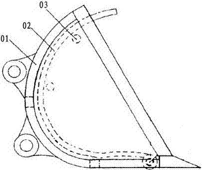
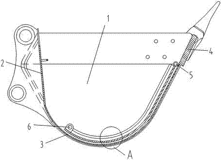
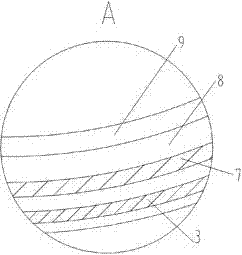
[0037] Such as Figure 2-Figure 7 As shown, a clay bucket of an excavator, the bucket body includes two parallel left side panels 1 and right side panels 10, the left side panels and the right side panels are connected by a transverse curved bottom panel 3 and a back panel 2 , the back plate is located behind the bottom plate, and the front edge of the bottom plate is provided with a main knife plate 4 . A scraper bucket and a wire rope 11 are arranged in the bucket body. The scraper includes an arc-shaped plate 7 that can be attached to the base plate and scrapers positioned at the left and right sides of the arc-shaped plate, and the scraper is vertically placed on the sides of the arc-shaped plate. The scraper includes a strip-shaped base plate 8 and a blade 9, and the blade of the scraper faces the mouth of the bucket and abuts against the side plate on the corresponding side, so as to cut off the clay on the side plate of the bucket body. Such as Figure 7 As shown, th...


PUM

PropertyMeasurementUnit
thicknessaaaaaaaaaa
Rockwell hardnessaaaaaaaaaa

Abstract

The invention provides a clay bucket for an excavator. The clay bucket for the excavator can achieve forcible soil discharge. A bucket body comprises a left side plate and a right side plate which are parallel. A transverse arc-shaped base plate and a back plate are connected between the left side plate and the right side plate. A main blade plate is arranged at the front edge of the base plate. A scraping bucket and a steel wire are arranged in the bucket body. The scraping bucket comprises an arc-shaped plate capable of being attached to the base plate and scrapers located at the left side and the right side of the arc-shaped plate. Each scraper comprises a strip-shaped substrate and a blade. The blade of each scraper faces a bucket opening and is attached to the side plate at the corresponding side. A whole cross section of the scraping bucket is in a in the shape of a left square bracket. An included angle portion of each scraper and the arc-shaped plate is in arc transition. The front edge of the arc-shaped plate is hinged with the front edge of the base plate. Two ends of the steel wire are respectively fixed on the rear edge of the arc-shaped plate and a lower surface of a bucket rod near the rear portion of a front hinged point of the bucket rod. When the arc-shaped plate is attached to the base plate tightly, the steel wire is in a tightened state. The left side plate and the right side plate are respectively provided with a limit block used for stopping further motion of the scraping bucket when the bucket reaches a maximal discharge angle.

Description

technical field [0001] The present invention relates to an excavator, in particular to a clay bucket of the excavator. Background technique [0002] The bucket is hinged at the front end of the arm, and the bucket rotates around the front hinge point of the arm through the bucket hydraulic cylinder and connecting rod. Its operation process is to cut the soil with the teeth of the bucket and load the soil into the bucket. After the bucket is full, it is lifted and rotated to the soil unloading position for unloading. After unloading, the bucket is rotated and lowered to the excavation surface for down dig once. Clay is easy to adhere to the middle and lower part of the side plate and the bottom plate of the bucket body, and the clay adhered to them is connected together, which makes the clay adhered in the bucket stronger, and it is not easy to unload the shovel head when unloading, thus prolonging the operation cycle time , reducing the effective bucket capacity. [000...

Claims


Application Information

Patent Timeline
Patent Type & Authority Applications(China)
IPC IPC(8): E02F3/42B23P15/00C25D11/02C21D1/773
Inventor 宋滕飞左臣明陈文赞赵修林崔滕吕庆立闵凡涛刘红建魏盼盼孙红
Owner 山东鲁班机械科技有限公司
Why Eureka
Try Eureka