Multistage dry vacuum pump

A dry vacuum pump, multi-stage cylinder technology, applied in the direction of rotary piston pumps, pumps, pump components, etc., can solve problems such as high cost, achieve the effects of overcoming leakage, enhancing cooling performance, and enhancing cooling performance

Active Publication Date: 2015-09-02
大卫金
View PDF3 Cites 5 Cited by
  • Summary
  • Abstract
  • Description
  • Claims
  • Application Information

AI Technical Summary

Problems solved by technology

[0011] According to the structure of the pump equipment, the inner accommodation space for housing the gas passage and the inner and outer cooling passages of the rotor is formed in an arc shape so that the heat exchange area for the air is maximized, thereby enhancing the cooling performance, and each cylinder is made of cast Made of steel, which results in enhanced cooling performance, enabling the desired cooling performance, thereby overcoming the problem of high cost once caused by the use of aluminum alloys in conventional air cooling systems

Method used


Image

  • Multistage dry vacuum pump
  • Multistage dry vacuum pump
  • Multistage dry vacuum pump

Examples


Embodiment Construction

[0034] Some preferred embodiments of the invention will be described with reference to the accompanying drawings.

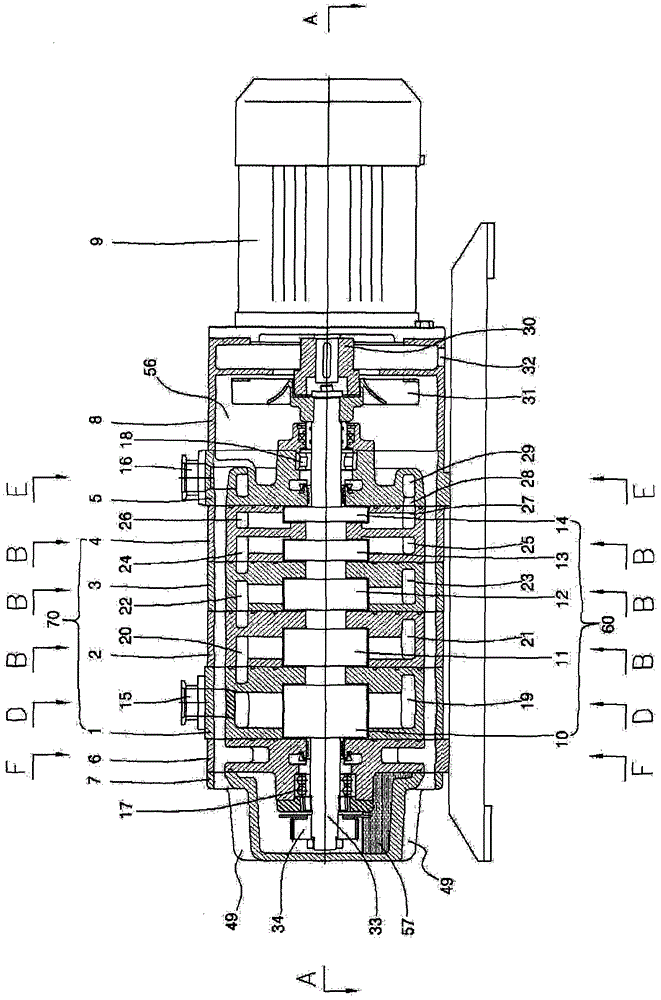
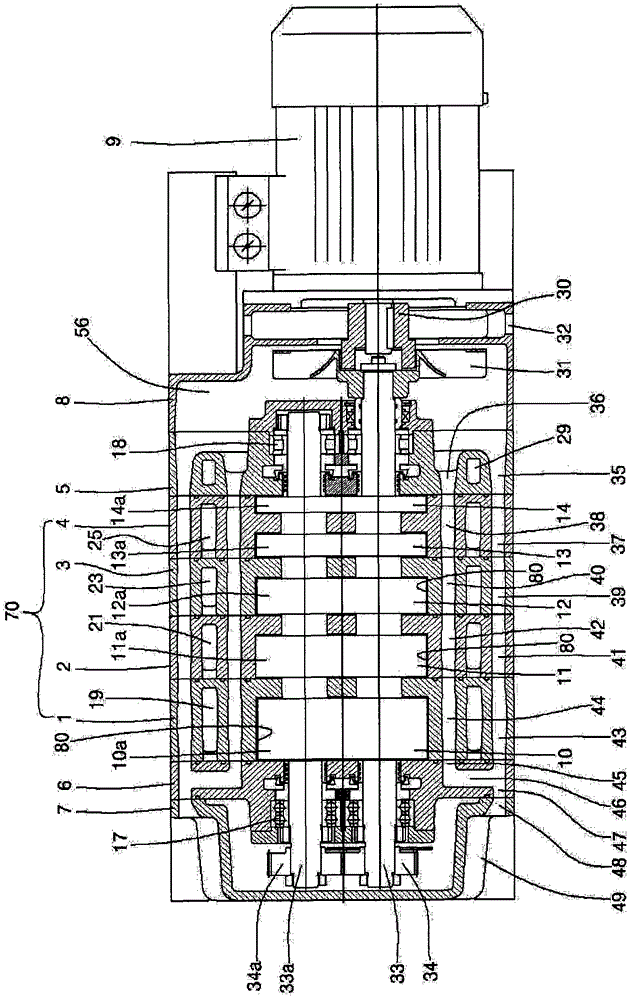
[0035] Figures 1 to 8 is a view showing a multi-stage dry vacuum pump according to the present invention, and the dry vacuum pump is a multi-stage Roots type in which a pair of pump rotors is accommodated in an inner accommodation space of each cylinder (casing).

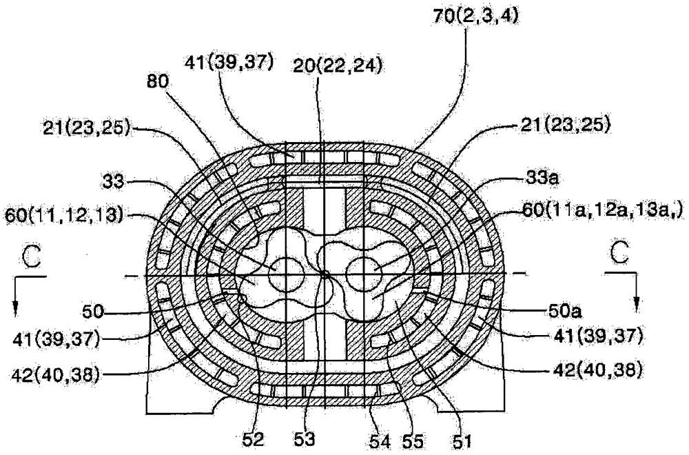
[0036] Such as figure 2As shown, the vacuum pump apparatus includes a pair of rotors 10, 11, 12, 13, 14 and 10a, 11a, 12a, 13a, 14a, 15a (hereinafter referred to by reference numeral 60) and is rotatably supported by bearings 17 and 18 The shafts 33 and 33a, and the pair of rotors are arranged in the peanut-shaped inner housing space 80 formed in the cylinders 1, 2, 3, 4. The rotors in each cylinder 1, 2, 3, 4 (indicated by reference numeral 70) are arranged at regular intervals and mounted on shafts 33 and 33a.

[0037] The vacuum pump includes a suction port 15 arranged on the upper side of the ...


PUM


Abstract

Disclosed is a multistage dry vacuum pump which is simple and compact in structure, needs only few components, is optimal in cooling performance, cheap in material cost, does not get thermally deformed, can completely discharge gas through increase of backpressure, and has increased facility vacuum degree. The multistage dry vacuum pump comprises multistage cylinder bodies, coupled rotors, coupled pump shafts, a motor, coupled gears, gas channels, internal cooling channels, external cooling channels and a cooling fan, wherein each multistage cylinder body has internal accommodation space, a sucking portion on one side and a discharging portion on the other side; the coupled rotors are accommodated in the internal accommodation space of the cylinder body and rotate in a mutually engagement manner; the coupled pump shafts are engaged with the rotors; the motor drives at least one pump shaft; the coupled gears are installed at the pump shafts and rotate synchronously with the shafts; the gas channels are communicated with the internal accommodation space of the multistage cylinder body and are formed into a spiral shape on an outer surface of each cylinder body; the internal cooling channels are formed into a concentric shape on inner sides of the gas channels, and axially penetrate through the cylinder bodies surrounding arc-shaped shafts on two sides of the internal accommodation space; the external cooling channels are concentrically surrounding arcs on outer sides of the gas channels; and the cooling fan is disposed at a connection part position of the motor and the pump shafts.

Description

technical field [0001] The present invention relates to a multi-stage dry vacuum pump, and more particularly to a dry screw type vacuum pump formed of two shafts and two rotors fixed to the shafts and rotating together, and thus improved by designing The cooling structure of the multi-stage dry vacuum pump is formed by multiple cylinders with successively increasing compression ratios. Background technique [0002] A vacuum pump generally refers to a device used to expel gas molecules from a sealed container and to increase the vacuum inside the container by sucking and compressing the gas at subatmospheric pressure and discharging it into the air. Vacuum pumps are classified into mechanical vacuum pumps and vapor pumps formed of a dry type and a wet type. The diffusion pump is a wet type that uses oil to achieve a high vacuum; while the mechanical vacuum pump is a dry type that has a low vacuum and does not use oil, so its structure is relatively simple and has good durabi...

Claims


Application Information

Patent Timeline
Patent Type & Authority Patents(China)
IPC IPC(8): F04C25/02F04C18/14F04C29/04
CPCF04C18/126F04C23/001F04C25/02F04C29/042F04C2210/22F04C2240/40Y10S415/00Y10S417/00
Inventor 大卫·金
Owner 大卫金
Why Eureka
Try Eureka