Composite oil cylinder and hydraulic machine with double action function with composite oil cylinder

A composite oil cylinder and oil cylinder technology, applied in the field of hydraulic machines, can solve the problems of increasing the tonnage and cost of hydraulic machinery, the influence of pressure tonnage, and poor dimensional accuracy of parts, and achieve the effects of simplifying design and manufacturing, reducing manufacturing costs and reducing deformation.

Inactive Publication Date: 2013-05-08
FOSHAN NANHAI XINGDI MACHINERY MFG
View PDF8 Cites 6 Cited by
  • Summary
  • Abstract
  • Description
  • Claims
  • Application Information

AI Technical Summary

Problems solved by technology

In addition to blankholder and stretching slider, the machine also needs stretching beam and blankholder beam. The structure of the machine is complicated, and the relative position accuracy between blankholder and drawing die is difficult to guarantee, so that the processed parts Dimensional accuracy is poor
[0006] The existing liquid-filled forming hydraulic press with an improved structure realizes the coaxial linkage of stretching and edge pressing, but it is realized through a structure calle

Method used


Image

  • Composite oil cylinder and hydraulic machine with double action function with composite oil cylinder
  • Composite oil cylinder and hydraulic machine with double action function with composite oil cylinder
  • Composite oil cylinder and hydraulic machine with double action function with composite oil cylinder

Examples


Embodiment Construction

[0025] In order to illustrate the content of the present invention more clearly, further description will be made below in conjunction with the accompanying drawings and specific embodiments:

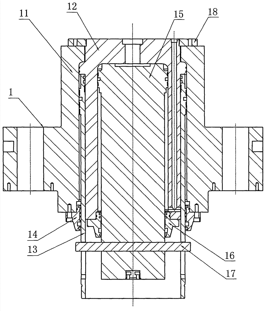
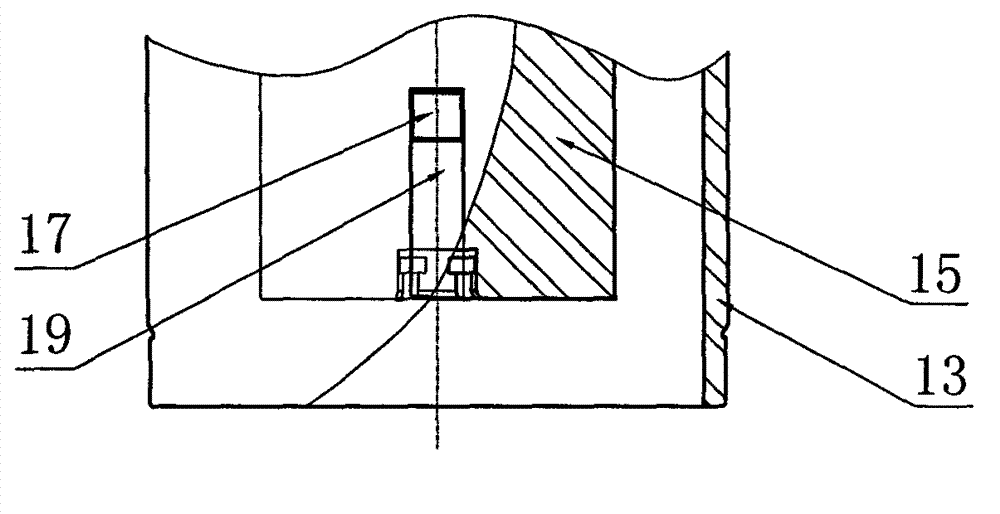
[0026] like figure 1 and figure 2 As shown, a composite oil cylinder 1 includes a primary cylinder system and a secondary cylinder system. The primary cylinder system includes the outer circle of a primary cylinder body 11, a secondary cylinder body 12, a primary cylinder piston rod 13 and a primary cylinder The guide sleeve 14 is composed of the first-stage cylinder body 11, the outer circle of the second-stage cylinder body 12, the first-stage cylinder piston rod 13 and the first-stage cylinder guide sleeve 14 to form a closed load-transmitting hydromechanical structural system, that is, an annular oil cylinder system The secondary oil cylinder system comprises the inner hole of the secondary cylinder body 12, the secondary cylinder piston rod 15 and the secondary cylinder guide sle...


PUM


Abstract

The invention belongs to the technical field of plate liquid filling forming, in particular to a composite oil cylinder and a hydraulic machine with a double action function with a composite oil cylinder. The composite oil cylinder comprises a one-level oil cylinder system and a two-level oil cylinder system. The two oil cylinder systems can be operated independently and are not disturbed with each other. The one-level oil cylinder system is a closed fluid mechanics structural system which is capable of transmitting loading, namely, an annular oil cylinder system. The two-level oil cylinder system is a closed fluid mechanics structural system which is capable of transmitting loading, namely, a traditional telescopic plunger type oil cylinder. A two-level cylinder body is locked tightly with a one-level cylinder body through locking nuts, thus two oil cylinder systems are formed. The two oil cylinder systems are free of relative movement and are not disturbed with each other. The two-level oil cylinder system is arranged in the inner portion of the one-level oil cylinder system. The composite oil cylinder is from outside to inside in sequence the one-level cylinder body, a one-level cylinder piston rod, the two-level cylinder body and a two-level cylinder piston rod. By means of the composite oil cylinder and the hydraulic machine with the double action function with the composite oil cylinder, the one-level oil cylinder system and the two-level oil cylinder are integrated into a whole. A walking beam is reduced and a complete machine structure is simplified. The composite oil cylinder and the hydraulic machine with the double action function with the composite oil cylinder are beneficial to reducing cost.

Description

technical field [0001] The invention belongs to the technical field of liquid-filled forming of plates, and in particular relates to a composite oil cylinder and a hydraulic press with double-acting functions with the composite oil cylinder. Background technique [0002] Hydroforming is a plastic processing technology that uses liquid pressure to form workpieces. According to the different materials used, it can be divided into three types: sheet metal hydroforming, shell hydroforming and tube blank hydroforming. The actual application of hydroforming technology in production began in the 1990s in developed countries abroad. In my country, Harbin Institute of Technology began to conduct special research in 1999, and the actual application in industrial production only began in recent years. In the hydraulic press industry, it is customary to call sheet metal hydraulic forming hydraulic presses liquid-filled hydraulic presses, shell hydraulic forming hydraulic presses water e...

Claims


Application Information

Patent Timeline
IPC IPC(8): F15B15/16B21D26/021
Inventor 曹广李经明罗毅年黎添沛何福宁
Owner FOSHAN NANHAI XINGDI MACHINERY MFG
Why Eureka
Try Eureka