Light-emitting diode (LED) energy-saving lamp

A technology of LED energy-saving lamps and energy-saving lamps, which is applied to lighting devices, light sources, electric light sources, etc., can solve problems such as low work efficiency, low efficiency, and increased cost, and achieve the effects of stable structure, high efficiency and accurate positioning.

Inactive Publication Date: 2013-05-08
ZHONGSHAN MLIGHT PHOTOELECTRIC +1
View PDF11 Cites 1 Cited by
  • Summary
  • Abstract
  • Description
  • Claims
  • Application Information

AI Technical Summary

Problems solved by technology

[0004] One is that the current automation equipment cannot complete the attachment of LED patches around the three-dimensional light source installation part, and the scattered LED patches must be pasted on the side and end surface of the patch seat one by one by hand, and the work efficiency is low;
[0005] The second is to manually solve the electrical connection problems between the scattered LED patches and the control circuit components, which also leads to low efficiency, increased cost, and poor stability;
[0006] The third is that the patch seat adopts a solid structure, which leads to difficulties in wiring the LED patch and control circuit components
[0008] Applicant finds no inspiration for the use of flexible circuit boards in energy-saving light bulbs

Method used


Image

  • Light-emitting diode (LED) energy-saving lamp
  • Light-emitting diode (LED) energy-saving lamp
  • Light-emitting diode (LED) energy-saving lamp

Examples


Embodiment 1

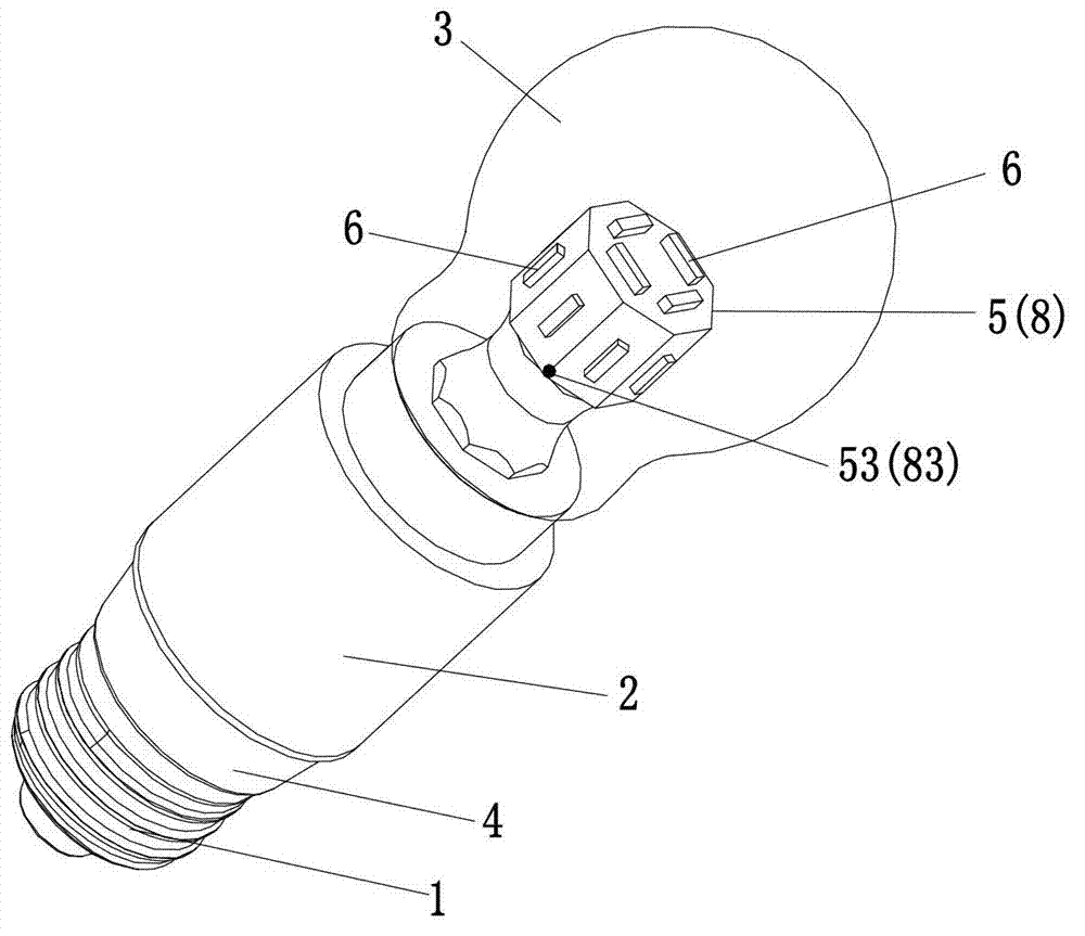
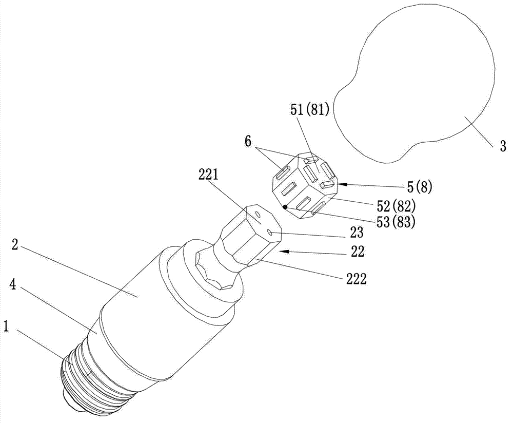
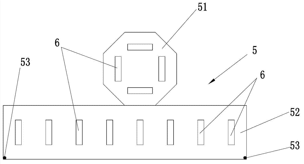
[0036] Such as figure 1 , figure 2 with image 3 As shown, the energy-saving lamp of this embodiment has an LED drive circuit (not shown in the figure), a lamp holder 1, a lamp holder 2, and a lamp shade 3. The lamp holder has two ends, one of which is the lamp holder mounting portion 21 and the other end is The LED light source mounting part 22 is in the form of an octagonal cylinder. The lampshade is mounted on the lamp holder and covers the LED light source and the light source mounting part. The lamp holder 1 is insulated and installed on the lamp holder mounting part 21 through an insulator 4, and the LED driving circuit contains The LED drive circuit is electrically connected to the lamp holder 1, the LED light source, and a single-sided flexible circuit board 5 is installed on the LED light source mounting portion 22 in an insulated manner. The flexible circuit board 5 is in the unfolded state. A first plate 51 and a second plate 52 are connected to each other, the LED l...

Embodiment 2

[0039] reference Figure 4 The difference between this embodiment and Embodiment 1 is that the shape of the flexible circuit board in the unfolded state is different. The shape of the first plate 71 of the flexible circuit board 7 of this embodiment is different from that of the first plate 51 of the flexible circuit board 5 of embodiment 1. . Both ends of the second plate 72 are provided with soldering points 73 insulated from the flexible circuit board circuit.

Embodiment 3

[0041] reference figure 1 , figure 2 , Figure 5 , The shape of the flexible circuit board 8 of this embodiment in the unfolded state is different from that of Embodiment 1. When the flexible circuit board is in the unfolded state, it presents a first plate 81 at the center position and a plurality of first plates diverging along the periphery of the first plate. Two plates 82, the first plate and the second plate of the flexible circuit board are both provided with LED patches 6, the first plate is installed on the end surface of the lamp holder, and each second plate is bent and installed along the edge of the lamp holder end surface On the side surface of the end of the lamp holder, each second plate and the LED patch on it are arranged around the side of the end of the lamp holder. The two sides of the second plate of the second plate of the flexible circuit board installed around the side of the end of the lamp holder are provided with welding points 83 insulated from the ...


PUM


Abstract

The invention discloses a light-emitting diode (LED) energy-saving lamp which comprises an LED light source, an LED drive circuit, a lamp head, a lamp base and a lampshade. The lamp base is provided with two end parts, wherein one end part of the lamp base is a lamp head installation part, and the other end part of the lamp base is an LED light source installation part. The lamp head is installed on the lamp head installation part in an insulation mode, and the LED light source is installed on the LED light source installation part. The LED energy-saving lamp is characterized by further comprising a flexible printed circuit board (FPCB) which is installed on the LED light source installation part in an insulation mode, the FPCB comprises a first board block and a second board block which are connected together, the LED light source is a plurality of LED patches, the plurality of LED patches are respectively arranged on the first board block and the second board block of the FPCB, the first board block is installed on the end face of the lamp base light source installation part, the second board block is installed around the lateral face of the lamp base light source installation part, the LED patches on the second board block are arranged around the lateral face of the lamp base light source installation part, and the LED drive circuit is electrically connected with the FPCB to supply power for the LED patches on the FPCB. The LED energy-saving lamp has the advantages of being stable in structure and convenient to manufacture.

Description

(1) Technical field: [0001] The invention relates to an LED energy-saving lamp. (2) Background technology: [0002] Chinese patent ZL201120278270.0, authorized announcement number CN202140877U discloses a SMD LED bulb, which includes a lamp cap, a lampshade, and a lamp cup connecting the lamp cap and the lampshade. The lamp cap is equipped with a control circuit assembly, and the lampshade is equipped with an LED patch. The patch is electrically connected to the control circuit assembly, a cylindrical base is installed in the lampshade, and a patch seat is fixed on the base, and the LED patch is pasted on the side and end surface of the patch seat; the patch seat adopts Solid structure or built-in radiating fins form a center-derived radiating structure. [0003] There are at least several inconveniences in the structure of the bulb: [0004] First, the current automated equipment cannot complete the placement of the LED patches around the three-dimensional light source installatio...

Claims


Application Information

Patent Timeline
Patent Type & Authority Applications(China)
IPC IPC(8): F21S2/00F21V23/00F21V19/00F21Y101/02
Inventor 文勇李艳
Owner ZHONGSHAN MLIGHT PHOTOELECTRIC
Why Eureka
Try Eureka