Fixed device and furnace body temperature measuring optical cable wiring method

A technology of fixing devices and wiring methods, which is applied in the direction of measuring devices, thermometers, measuring heat, etc., to achieve the effects of prolonging service life, simple construction, and saving construction costs

Inactive Publication Date: 2013-05-08
WUHAN NORTHERN OPTOELECTRONICS
View PDF10 Cites 2 Cited by
  • Summary
  • Abstract
  • Description
  • Claims
  • Application Information

AI Technical Summary

Problems solved by technology

[0004] The technical problem to be solved by the present invention is to provide a fixing device that can reduce the measurement error caused by thermal expansion and contraction of th

Method used


Image

  • Fixed device and furnace body temperature measuring optical cable wiring method
  • Fixed device and furnace body temperature measuring optical cable wiring method
  • Fixed device and furnace body temperature measuring optical cable wiring method

Examples


Embodiment 1

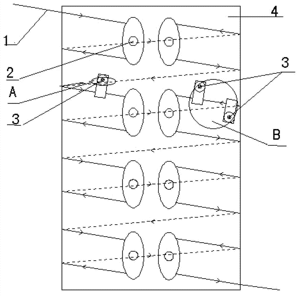
[0024] Such as figure 1 As shown, the present embodiment provides a method for wiring a furnace body temperature measurement optical cable, which is used for wiring on a furnace body with a connecting pipe 5, and only performs wiring and temperature measurement on the furnace body 4, and in the furnace body 4 Two rows of first fixing devices 2 and first nuts 21 arranged perpendicular to the ground plane are welded on the surface, and the distance between adjacent first fixing devices 2 is 500mm. The arc-shaped spring pieces 22 corresponding to the two rows of first fixing devices 2 are respectively relatively placed. The optical cable 1 is bypassed on the arc spring piece 22 of the first first fixing device 2 in the first row at the starting point of the wiring, reversely wound to the first first fixing device 2 in the second row, and from the second row to the first fixing device 2. The arc-shaped spring piece 22 of the first first fixing device 2 in the first row is bypasse...

Embodiment 2

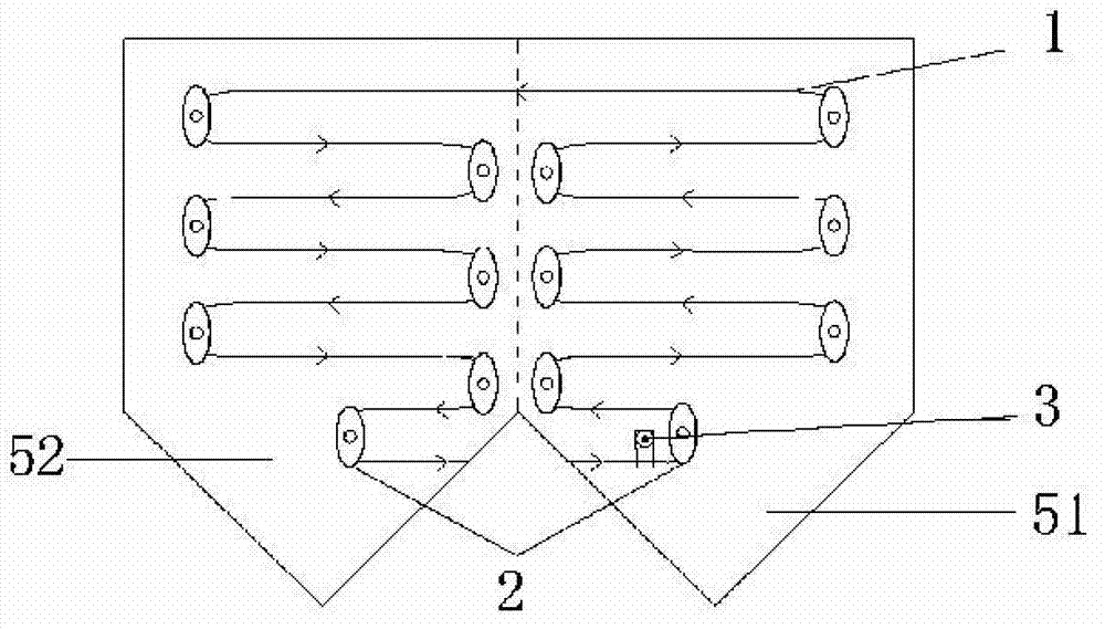
[0026] Such as figure 2 As shown, this embodiment provides another method for wiring the furnace body temperature measuring optical cable. Compared with Embodiment 1, this embodiment, in addition to the temperature measurement of the furnace body 4 wiring as in Embodiment 1, also measures the temperature of the furnace body 4. The connecting pipe 5 of the body is used for wiring temperature measurement. Such as image 3 As shown, the connecting pipe 5 of the furnace body is divided into a first part 51 and a second part 52 from the axial direction. The surface of the second part 52 is welded with two rows of first fixing devices 2 respectively, and the first nut 21 is welded at each turn of the serpentine cable wiring; At the same time, the first part 51 on the furnace body connecting pipe 5 is bypassed on each of the first fixing device arc-shaped spring pieces 22 in turn, so that the optical cable is wound from the furnace body connecting pipe 5 head to the furnace body c...


PUM


Abstract

The invention belongs to the technical field of a distributed type sensing temperature measuring, and particularly relates to a fixed device and a furnace body temperature measuring optical cable wiring method. Wiring is conducted on a furnace body with a connection pipe, two columns of first nuts are welded on the surface of a main body of the furnace body, corresponding arc-shaped spring pieces of two columns of first fixed device are respectively arranged relatively, an optical cable is begun winding from a first fixed device of a first of a first column of a wiring starting point place and wound on a first fixed device of a first of a second column in a reversed mode, and the optical cable is repeatedly wound until winding on the wiring terminal point place. Tabletting discs of the first fixed devices are pressed on each arc-shaped spring piece, the first nuts are respectively used to fasten the first fixed devices, and the second fixed devices are utilized to fix concave-convex uneven place of the furnace body. When wiring of the optical cable is conducted, the problem that the optical cable is expanded with heat and contracted with cold is solved by installing of the first fixed devices, and one optical cable can be adopted to conduct wiring from start to finish. The problem of measuring precision of the connection place of the main body and the connection pipe and the concave-convex uneven place of the furnace body is solved by installing of the second fixed devices.

Description

technical field [0001] The invention belongs to the technical field of distributed sensing temperature measurement, and in particular relates to a fixing device and a furnace body temperature measurement optical cable wiring method, which is suitable for measuring the surface temperature of large and medium-sized high-temperature furnace bodies such as blast furnaces, converters, and gasification furnaces. Background technique [0002] During the production and operation of large and medium-sized high-temperature furnaces such as blast furnaces, converters, and gasifiers, the temperature of the furnace body surface is usually measured for safety reasons. The two most commonly used temperature measurement technologies are distributed fiber optic temperature measurement and thermocouple temperature measurement. Among them, the principle of the distributed optical fiber temperature measurement system to obtain the spatial temperature distribution information is: the use of ligh...

Claims


Application Information

Patent Timeline
IPC IPC(8): G01K11/32G01K11/324
Inventor 杨欢许慧敏张栓民
Owner WUHAN NORTHERN OPTOELECTRONICS
Why Eureka
Try Eureka