Supercharge Your Innovation With Domain-Expert AI Agents!

a photolithography mask

A photolithography mask and reverse-shape lithography technology, applied in optics, components for photomechanical processing, instruments, etc., can solve problems such as silicon nitride residue, incomplete exposure of wafer edge areas, and reduced chip yield , to overcome the effect of silicon nitride residue

Active Publication Date: 2016-08-31
WUXI DISI MICROELECTRONICS CO LTD
View PDF8 Cites 0 Cited by
  • Summary
  • Abstract
  • Description
  • Claims
  • Application Information

AI Technical Summary

Problems solved by technology

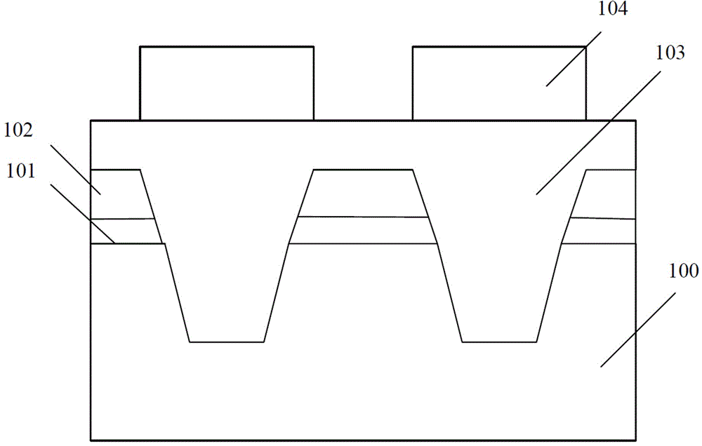
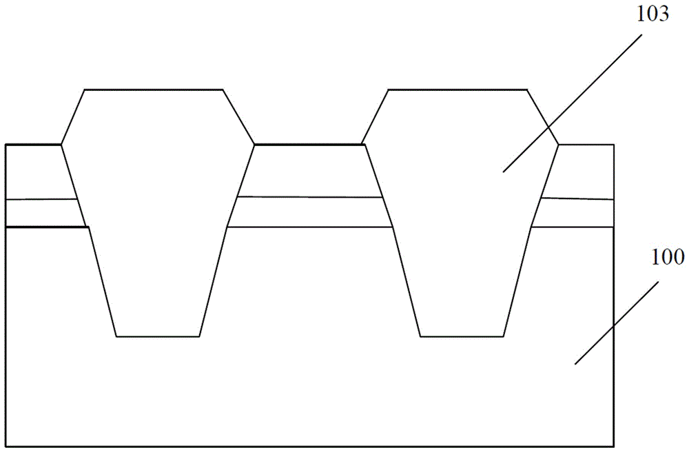
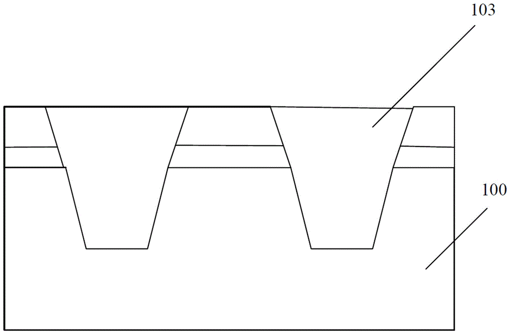
In order to solve the above-mentioned problem of silicon nitride residue, in the prior art, the layout of the chip on the wafer is usually changed to avoid incomplete exposure of the edge area of ​​the wafer.
like figure 2 As shown in the figure below, position the chip on the edge of the wafer that needs to be exposed as close as possible to the inside. Although the above solution can expose the chip on the edge of the wafer and overcome the problem of silicon nitride residue in the above-mentioned STI manufacturing process, the edge area of ​​the wafer The focus function is not good, and the yield of chips located at the edge of the wafer will be reduced
[0006] Therefore, there is an urgent need to propose a photolithography mask, which can overcome the problem of silicon nitride residue in the incomplete exposure area of ​​the wafer edge while satisfying the normal focus function of the wafer edge

Method used


Image

  • a photolithography mask
  • a photolithography mask
  • a photolithography mask

Examples


Embodiment Construction

[0028] In the following description, numerous specific details are given in order to provide a more thorough understanding of the present invention. It will be apparent, however, to one skilled in the art that the present invention may be practiced without one or more of these details. In other examples, some technical features known in the art are not described in order to avoid confusion with the present invention.

[0029] In order to provide a thorough understanding of the present invention, in the following description, detailed steps will be set forth in order to illustrate the present invention. Obviously, the practice of the invention is not limited to specific details familiar to those skilled in the semiconductor arts. Preferred embodiments of the present invention are described in detail below, however, the present invention may have other embodiments besides these detailed descriptions.

[0030] It should be understood that when the terms "comprising" and / or "com...


PUM


Abstract

The invention provides a lithographic mask. The lithographic mask comprises a main pattern located in the center of the mask and a light-transmission auxiliary pattern located at the edge of the mask. The minimum distance between the main pattern and the light-transmission auxiliary pattern guarantees that when the zones with the different patterns are subjected to lithographic exposure, mutual interference is avoided. The lithographic mask can satisfy requirements of the normal focusing function of wafer edges, and solves the problem of silicon nitride residues in imperfect exposure zones at the wafer edges.

Description

technical field [0001] The present invention relates to a semiconductor device, in particular to a photolithographic mask or a photolithographic plate (reticle). Background technique [0002] With the continuous innovation of integrated circuit manufacturing technology, the size of various components in integrated circuits is continuously reduced, while the functional density is continuously increased. The most important part of the entire semiconductor manufacturing process can be said to be the photolithography manufacturing process, which is widely used in various steps of the semiconductor manufacturing process. In addition, whether the integration of components in the entire semiconductor industry can continue to be smaller than 0.18µm. Wide progress also depends on the development of lithography manufacturing process. [0003] At present, STI (Shallow Trench Isolation) process and CMP (Chemical Mechanical Polishing) process are widely used in semiconductor processes b...

Claims


Application Information

Patent Timeline
IPC IPC(8): G03F1/38
Inventor 黄玮
Owner WUXI DISI MICROELECTRONICS CO LTD
Features
  • R&D
  • Intellectual Property
  • Life Sciences
  • Materials
  • Tech Scout
  • Unparalleled Data Quality
  • Higher Quality Content
  • 60% Fewer Hallucinations
Learn More