Simulated optical fiber demonstrating device

A technology for simulating optical fibers and demonstration devices, which is applied in the field of analog optical fiber demonstration devices, can solve the problems that beginners are difficult to obtain perceptual cognition, and achieve the effects of good demonstration effect, low preparation cost and simple main structure

Inactive Publication Date: 2013-05-08
QINGDAO UNIV
View PDF5 Cites 9 Cited by
  • Summary
  • Abstract
  • Description
  • Claims
  • Application Information

AI Technical Summary

Problems solved by technology

But so far, no device demonstrating the propagation of light in the optical fiber has been disclosed. The reason is that not only the refractive index of the fiber core is greater than the refractive index of the cladding, but also the square root of the square difference between the two refractive indices must be less than 1. That is, the numerical aperture is less than 1. In daily life and conventional devices, there is no device or device with such a refractive index distribution.
The lecturer's treatment of this part of the content is mainly theoretical explanation, combined with drawing, it is difficult for beginners to obtain perceptual cognition, and such a demonstration device is urgently needed in the practical teaching of optics to fill in the blank

Method used


Image

  • Simulated optical fiber demonstrating device
  • Simulated optical fiber demonstrating device

Examples


Embodiment

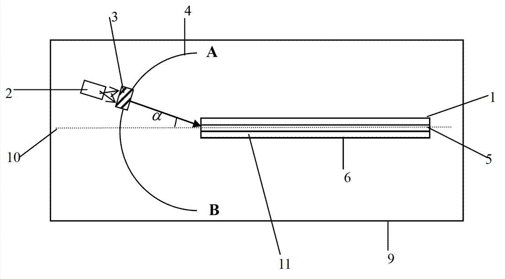
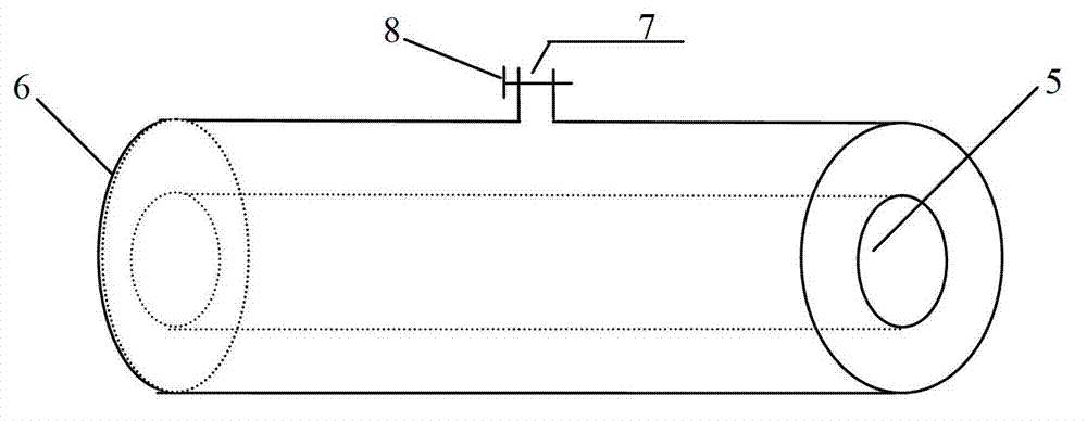
[0011] The main structure of this embodiment includes an analog optical fiber 1, a visible light source 2, a collimator 3, an arc slideway 4, a solid glass cylinder 5, a cylindrical glass container 6, a water injection port 7, a water injection valve 8, a smooth white board 9, Center line 10 and filling liquid 11; the center line 10 places of the smooth white board 9 of rectangular wooden or metal structure parallel to the long side is pasted and fixedly installed with simulated optical fiber 1, and the main body of simulated optical fiber 1 is a cylindrical structure, and its periphery is made of There is a cylindrical glass container 6 of inner hollow type glass, and a solid glass cylinder 5 is formed on the coaxial center of the cylindrical glass container 6. The inner diameter of the cylindrical glass container 6 is greater than the outer diameter of the solid glass cylinder 5. Between the two Filling liquid 11 is filled in the space between; The front end of the upper side...


PUM


Abstract

The invention belongs to the technical field of optical equipment and relates to a simulated optical fiber demonstrating device. A simulated optical fiber is arranged on the central line, parallel to the long side of a smooth white board, of the smooth white board. A main body of the simulated optical fiber is in a cylinder structure. A cylindrical glass container is arranged on the periphery of the simulated optical fiber. A solid glass cylinder is arranged in the cylindrical glass container and is coaxial with the cylindrical glass container. The inner diameter of the cylindrical glass container is bigger than the outer diameter of the solid glass cylinder. A space between the cylindrical glass container and the cylindrical glass container is filled with filling liquid. A collimation regulator is fixedly arranged at the front end of the upper side of the central line of the smooth white board. A visible light source is arranged corresponding to the outer side of the collimation regulator. An arc-shaped slideway is fixedly arranged at the front end of the simulated optical fiber. The front end point of the simulated optical fiber coincides with the center of the arc-shaped slideway. The collimation regulator is fixed on the arc-shaped slideway and slides along the arc-shaped slideway. The simulated optical fiber is formed by the cylindrical glass container, the solid glass cylinder and the filling liquid in a coaxially combined mode. The simulated optical fiber demonstrating device is simple in structure of the main body, reliable in principle, low in manufacturing cost, good in demonstration effects and environment-friendly.

Description

Technical field: [0001] The invention belongs to the technical field of optical equipment, and relates to a demonstration device for simulating the propagation path of light in an optical fiber core, in particular to a demonstration of the total reflection phenomenon of light in a step-type multimode optical fiber. Background technique: [0002] The geometrical optics principle of optical fiber light guide is the total reflection of light. The refractive index of the fiber core is greater than that of the cladding. Since the diameter of the fiber is only a few to a hundred microns, the human eye cannot see the propagation path of the light beam in the fiber core. At present, most science colleges have set up the course "Optical Fiber Communication Principles". Some high schools will also teach students the basic principles of optical fiber communication in order to expand students' knowledge. The training and setting of communication companies also need to demonstrate the li...

Claims


Application Information

Patent Timeline
Patent Type & Authority Applications(China)
IPC IPC(8): G09B23/22
Inventor 潘淑娣刘建华葛晓辉宋然然
Owner QINGDAO UNIV
Why Eureka
Try Eureka