Anti-icing voltage-sharing plate

An anti-icing and pressure plate technology, applied in the direction of suspension/strain insulators, electrical components, insulators, etc., can solve the problem of the size of the tower window, the increase of the line corridor channel, the difficulty of effectively protecting the safety of the power grid, and the inability of the power grid to be effectively deployed To achieve the effect of delaying the icing package time, increasing the icing flashover voltage, reducing the window size and line corridor

Inactive Publication Date: 2013-05-08
STATE GRID HUNAN ELECTRIC POWER CO LTD ELECTRIC POWER SCI RES INST +2
View PDF5 Cites 5 Cited by
  • Summary
  • Abstract
  • Description
  • Claims
  • Application Information

AI Technical Summary

Problems solved by technology

Extending the length of the insulator string requires that the original line must be abolished and then the tower must be re-erected, and the window size of the iron tower and the corridor of the line are required to be significantly increased. The reconstruction cost is high, it is very complicated, and the operation is difficult. It cannot be fully and effectively deployed on the power grid. Therefore, it is difficult to effectively protect the operation safety of the power grid; and the intervening layout is currently only used in lines of 220kV and below. For lines above 500kV using large-tonnage insulators, due to the lack of aerodynamic insulators for flower arrangement, It is still not possible to use an interleaved arrangement to improve ice resistance

Method used


Image

  • Anti-icing voltage-sharing plate
  • Anti-icing voltage-sharing plate
  • Anti-icing voltage-sharing plate

Examples


Embodiment Construction

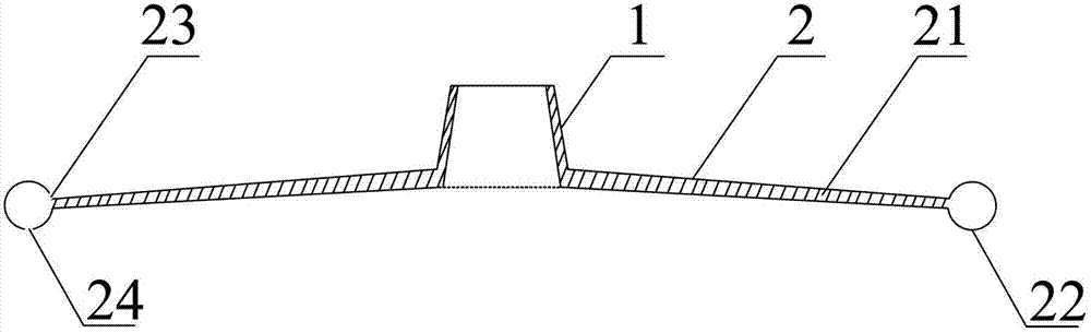
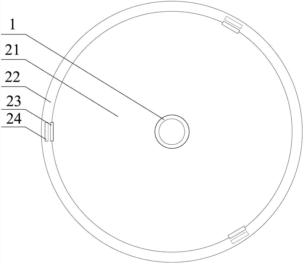
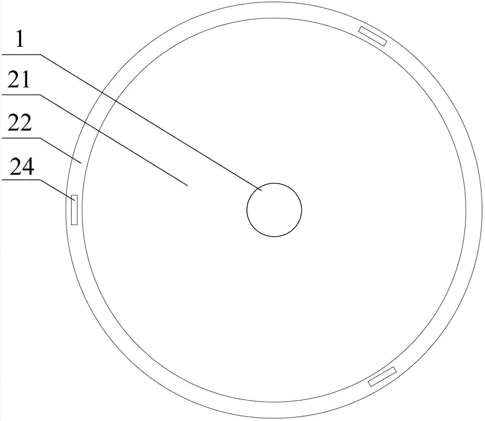
[0022] See Figure 1~3 , figure 1 Shown is a specific embodiment of the present invention. In the anti-icing equalizing plate of this embodiment, one of the components of the cover 1 is in the shape of a bowl, which is cut and welded from a 45# plate. The outer diameter of the upper bottom surface is φ80mm, and the lower bottom surface is the hood caliber φ100mm, and the height is 80mm. Another component disc 2 such as figure 1 As shown, there is an umbrella-shaped disk body 21 with a center hole so that it has a center hole. The outer periphery of the umbrella-shaped disc body 21 is a ring body 22 with a circular cross section. The disc 21 inside the ring 22 is like figure 2 As shown, drainage holes 23 are evenly distributed. The bottom surface of the ring body 22 is like image 3 As shown, the lower edge drainage holes 24 are evenly distributed. The aperture size of the central hole of the disc 2 matches the aperture size of the cover body 1. The cover body 1 is fixed ...


PUM


Abstract

The invention provides an anti-icing voltage-sharing plate. The anti-icing voltage-sharing plate is composed of a bowl-shaped cover body (1) and an umbrella cover-shaped disk (2), wherein the umbrella cover-shaped disk is provided with center holes. The cover body is fixedly connected with the center holes of the disk (2) through a cover opening of the cover body in a butt joint mode. The disk (2) is provided with an umbrella cover-shaped disk body (21). The edge of The disk body (21) is a circular body (22). Drain holes (23) are formed in the edge of the disk body (21) inside the circular body (22). Lower edged drain holes (24) are formed in the lower surface of the circular body (22). The anti-icing voltage-sharing plate has the advantages that icing coating time can be delayed to more than 10-15 times to increase the icing flashover voltage by 18%-25% in the area which electric transmission line are polluted heavily; rain flashover caused by rain curtains formed by the pollutants of the top of the tower can be avoided; pollution flashover caused by bird droppings can be avoided; thunderstrike flashover voltage can be enhanced; the sizes of the windows of towers and line corridors can be decreased and investment can be saved.

Description

Technical field [0001] The invention belongs to the technical field of electric power engineering, and in particular relates to an anti-icing equalizing plate for delaying the bridging time of icing and icing and increasing the power frequency flashover voltage of icing. Background technique [0002] my country is one of the countries with the most severe icing on transmission lines in the world. Severe icing will lead to a sharp decline in the mechanical and electrical performance of transmission lines, leading to icing accidents. According to incomplete statistics, there have been thousands of large and small icing accidents on transmission lines since 1954. For example, the continuous low-temperature rain and snow that occurred in southern my country in January 2008 caused serious icing of transmission lines, with an average thickness of more than 30mm, causing a large number of transmission lines to have insulator icing flashover trips, seriously affecting the safe operation...

Claims


Application Information

Patent Timeline
Patent Type & Authority Applications(China)
IPC IPC(8): H01B17/04H01B17/48H01B17/52
Inventor 巢亚锋黄福勇
Owner STATE GRID HUNAN ELECTRIC POWER CO LTD ELECTRIC POWER SCI RES INST
Why Eureka
Try Eureka