A power control method, system and device for a sounding reference signal

A detection reference signal and power control technology, applied in the field of communication, can solve problems such as inaccurate calculation of path loss, inability to meet user coverage and reception quality requirements, and other user interference.

Active Publication Date: 2018-06-19
ZTE CORP
View PDF4 Cites 0 Cited by
  • Summary
  • Abstract
  • Description
  • Claims
  • Application Information

AI Technical Summary

Problems solved by technology

However, in CoMP scenarios 3 and 4, due to the imbalance of transmit power among cells, according to the principle of maximum receive gain, the set of downlink CoMP transmit nodes and the set of uplink CoMP receive nodes of the user are not the same, so the downlink path loss It is not equal to the uplink path loss, so the path loss calculation is not accurate, resulting in a large deviation in the open-loop power control, so that the fine-tuning of the closed-loop still cannot obtain a good power control effect in time
If the path loss calculation is too large, it will not only waste the user's transmission power, but also cause greater interference to other users; on the contrary, if the path loss calculation is too small, it may not be able to meet the coverage and reception quality requirements required by the user

Method used


Image

  • A power control method, system and device for a sounding reference signal
  • A power control method, system and device for a sounding reference signal
  • A power control method, system and device for a sounding reference signal

Examples


Embodiment 1

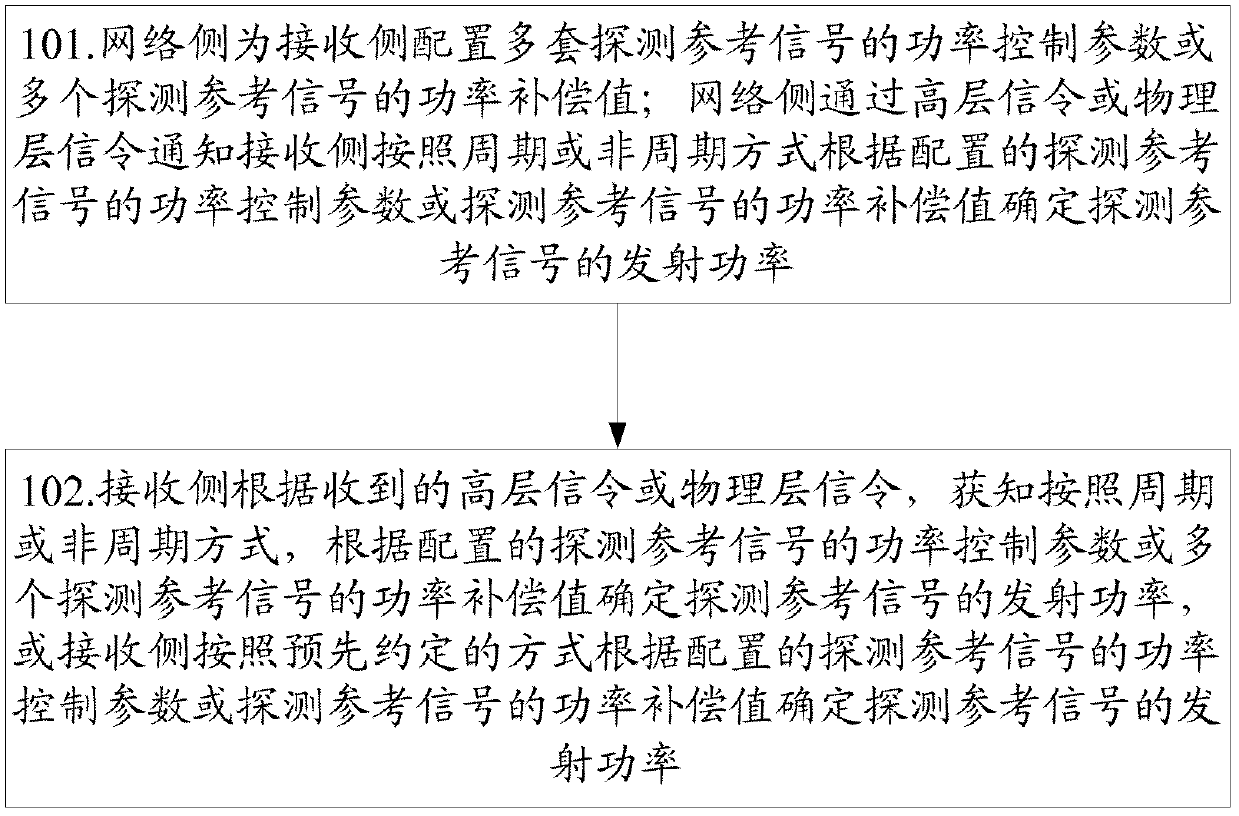
[0458] The network side configures three SRS power compensation values ​​ΔP1, ΔP2, and ΔP3 for the receiving side through high-level signaling, which are used for SRS power compensation when the receiving side is in the non-CoMP state, uplink CoMP state, and downlink CoMP state, respectively.

[0459] The network side configures and notifies the receiving side of the SRS power control parameters in the non-CoMP state according to the existing method, and the SRS power control parameters in the non-CoMP state include at least: P SRS_OFFSET,c , represents the power offset of SRS in each subframe; M SRS,c , indicating the transmission band of SRS in each subframe; P O_PUSCH,c , represents the PUSCH power control parameter; α c , represents the path loss conversion factor; f c , indicating the closed-loop power control correction value of the SRS.

[0460] The receiving side calculates the uplink path loss PL according to the existing method c .

[0461] The network side noti...

Embodiment 2

[0482] The network side configures 3 sets of SRS power control parameters (the first set of SRS power control parameters, the second set of SRS power control parameters, and the third set of SRS power control parameters) for the receiving side through high-level signaling, which are respectively used for the receiving side in non-CoMP state, uplink CoMP state, and SRS power control in downlink CoMP state.

[0483] Each set of SRS power control parameters includes at least: P SRS_OFFSET,c , indicating the power offset of the SRS in each subframe; M SRS,c , indicating the transmission bandwidth of SRS in each subframe; P O_PUSCH,c , represents the PUSCH power control parameter; α c , represents the path loss conversion factor; f c , indicating the closed-loop power control correction value of the SRS.

[0484] The receiving side determines the uplink path loss PL according to the existing method or a new method c .

[0485] The network side notifies the receiving side of i...

Embodiment 3

[0500] The network side configures 3 sets of SRS power control parameters (the first set of SRS power control parameters, the second set of SRS power control parameters, and the third set of SRS power control parameters) for the receiving side through high-level signaling, which are respectively used for the receiving side in non-CoMP state, uplink CoMP state, and SRS power control in downlink CoMP state.

[0501] Each set of SRS power control parameters includes at least: P SRS_OFFSET,c , for the power offset of SRS in each subframe; M SRS,c , used for the transmission bandwidth of SRS in each subframe; P O_PUSCH,c , used for PUSCH power control parameters; α c , used for path loss conversion factor; f c , used for the closed-loop power control correction value of SRS.

[0502] The receiving side determines the uplink path loss PL according to the existing method or a new method c .

[0503] The network side and the receiving side cyclically determine the transmit power...


PUM


Abstract

Disclosed are a power control method, system and device for a sounding reference signal. One method includes: the network side configuring for the receiving side power control parameters of a plurality of sets of sounding reference signals or power compensation values of a plurality of sounding reference signals; the network side notifying the receiving side to determine the transmit power of the sounding reference signal through a high layer signalling or a physical layer signalling according to a periodical or non-periodical manner and according to the power control parameters of the sounding reference signals or the power compensation values of the sounding reference signals. Another method includes: the network side configuring for the receiving side power control parameters of a plurality of sets of sounding reference signals or power compensation values of a plurality of sounding reference signals; the receiving side determining the transmit power of the sounding reference signal according to a predetermined manner and according to the power control parameters of the sounding reference signals or the power compensation values of the sounding reference signals. The technical solution according to the present invention can realize transmit power control to the sounding reference signal more accurately and flexibly.

Description

technical field [0001] The present invention relates to the communication field, in particular to a power control method, system and device for a sounding reference signal. Background technique [0002] The evolved Long Term Evolution (LTE-A, Long Term Evolution-Advanced) system uses Orthogonal Frequency Division Multiplexing (OFDM, Orthogonal Frequency Division Multiplexing) as the basic multiple access multiplexing method for the uplink and downlink of the system. Unlike traditional wireless communication systems based on code division multiple access (CDMA, Code Division Multiple Access) multiple access multiplexing, the LTE-A system has no processing gain, and there is almost no interference in the cell because it is completely frequency-division orthogonal. problem, but the handling of the interference problem at the edge of the cell is relatively tricky. Coordinated Multiple Point (CoMP, Coordinated Multiple Point) technology is to use the transmit antennas of multipl...

Claims


Application Information

Patent Timeline
Patent Type & Authority Patents(China)
IPC IPC(8): H04W52/14H04W52/40
CPCH04W52/325H04W52/146
Inventor 弓宇宏孙云锋李书鹏
Owner ZTE CORP
Why Eureka
Try Eureka