
gear pump

A gear pump, gear technology, applied in the direction of pumps, pump components, rotary piston pumps, etc., can solve problems such as uneven delivery flow

Active Publication Date: 2016-03-30
OERLIKON TEXTILE GMBH & CO KG
View PDF6 Cites 0 Cited by
  • Summary
  • Abstract
  • Description
  • Claims
  • Application Information

AI Technical Summary

Problems solved by technology

This phenomenon leads directly to inhomogeneities in the delivery flow during one revolution of the pump shaft

Method used


Image

  • gear pump
  • gear pump
  • gear pump

Examples


Embodiment Construction

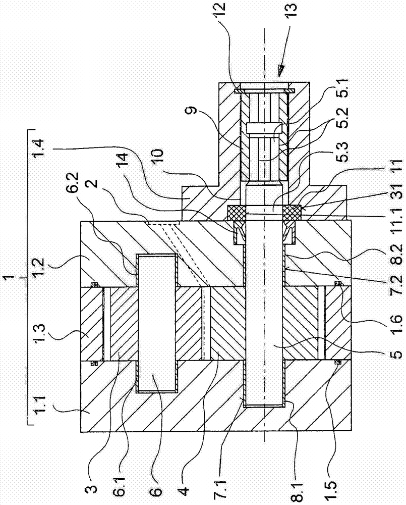
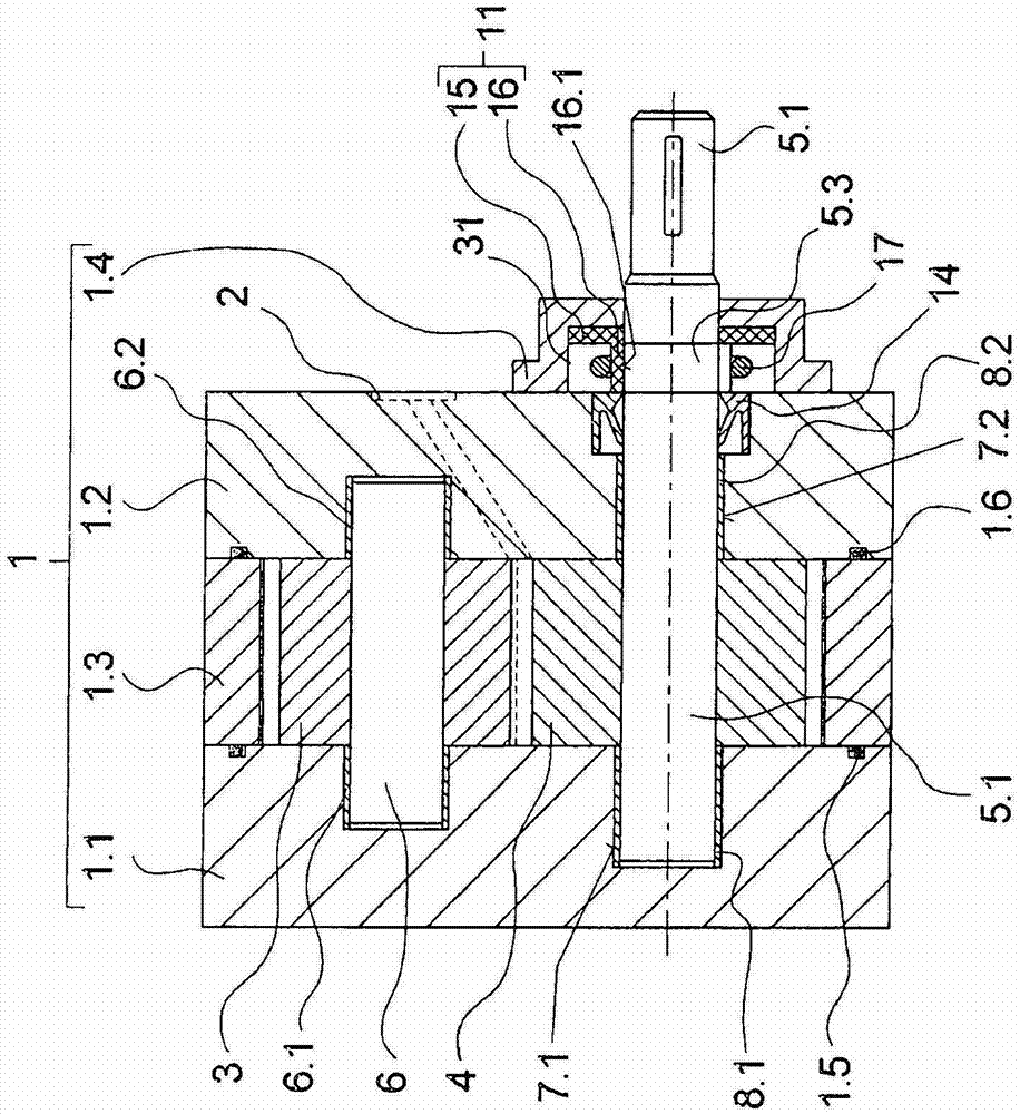
[0023] figure 1 Shown is a first embodiment of a gear pump according to the invention. The gear pump comprises a pump casing 1 . The pump housing 1 is multi-part and has a plurality of housing plates 1.1, 1.2 and 1.3 and a shaft housing 1.4. The central housing plate 1.3 contains recesses for the two intermeshing gearwheels 3 and 4. The central housing plate 1.3 is held together with the gear wheels 3 and 4 between the outer housing plates 1.1 and 1.2. In each case a sealing ring 1.5 and 1.6 is arranged in the end faces of the outer housing plates 1.1 and 1.2, by means of which sealing rings the gap between the central housing plate 1.3 and the outer housing plates 1.1 and 1.2 is sealed to the outside.

[0024] One of the gears 3 is fixedly connected to a rotatable bearing shaft 6 . The bearing shaft 6 is held in two bushings 6.1 and 6.2 which are inserted into the outer housing plates 1.1 and 1.2. The second gear wheel 4 is held on the pump shaft 5 in a non-rotatable man...


PUM


Abstract

A gear pump includes a plurality of gear wheels rotatably retained in a pump housing and that engage in one another for the conveyance of a medium. One of the gear wheels is driven by a pump shaft, which can be coupled to a drive by means of a coupling end. To maintain a uniform conveyance flow, in particular with strongly fluctuating operational pressures, during alternating load states, within a single rotation, a brake ring is disposed on the circumference of the pump shaft, which acts with at least one brake surface on a friction surface of the pump shaft or on a friction surface of the pump housing.

Description

technical field [0001] The invention relates to a gear pump. Background technique [0002] The use of gear pumps for conveying and metering fluids is known, in which the medium to be conveyed is conveyed between the pump suction and the pump discharge by the engagement of two gears which mesh with each other. As a result, the delivery rate can be adjusted very uniformly by means of multiple delivery stages, so such gear pumps are preferably used to generate a uniform delivery rate, such as for supplying paint in painting plants. [0003] Such a gear pump is known, for example, from DE 10 2005 059 563 A1. In this known gear pump, two intermeshing gears are held rotatably in a pump housing and are connected to the pump shaft. The pump shaft protrudes with a coupling end from the pump housing and can be coupled to the drive shaft of the motor. Inhomogeneities in the delivery flow are observed when using such gear pumps with varying pressure loads on the discharge side or the...

Claims


Application Information

Patent Timeline
Patent Type & Authority Patents(China)
IPC IPC(8): F04C2/14
CPCF04C2/14F04C13/005F04C15/0084F04C2/02F04C2/08F04C2/344F04C11/00F04C15/0026F04C18/16F04C28/24F04C2210/20F04C2240/30Y10S415/00Y10S417/00
Inventor U·黑尔宾A·托姆齐克D·维茨勒
Owner OERLIKON TEXTILE GMBH & CO KG
Learn More