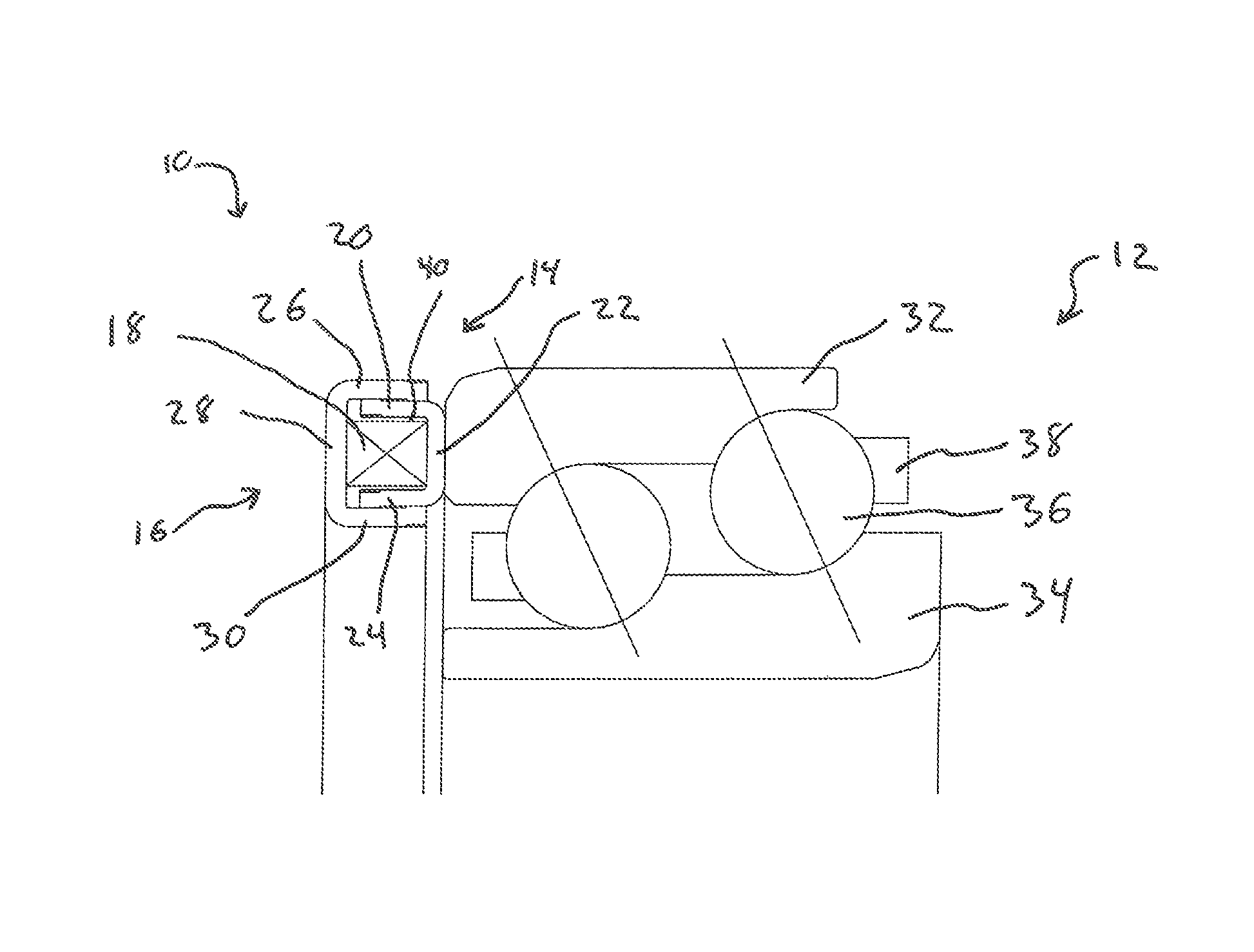
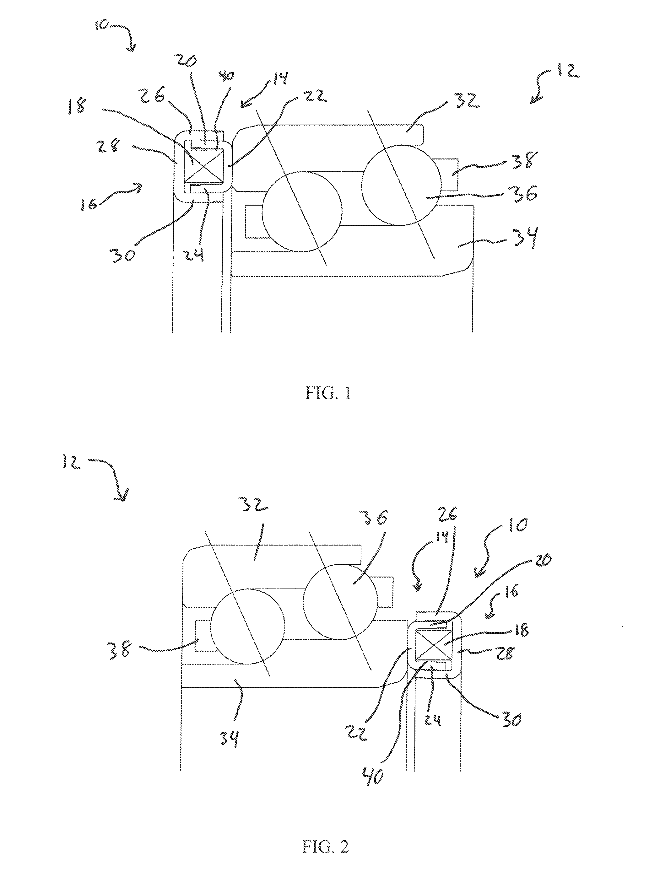
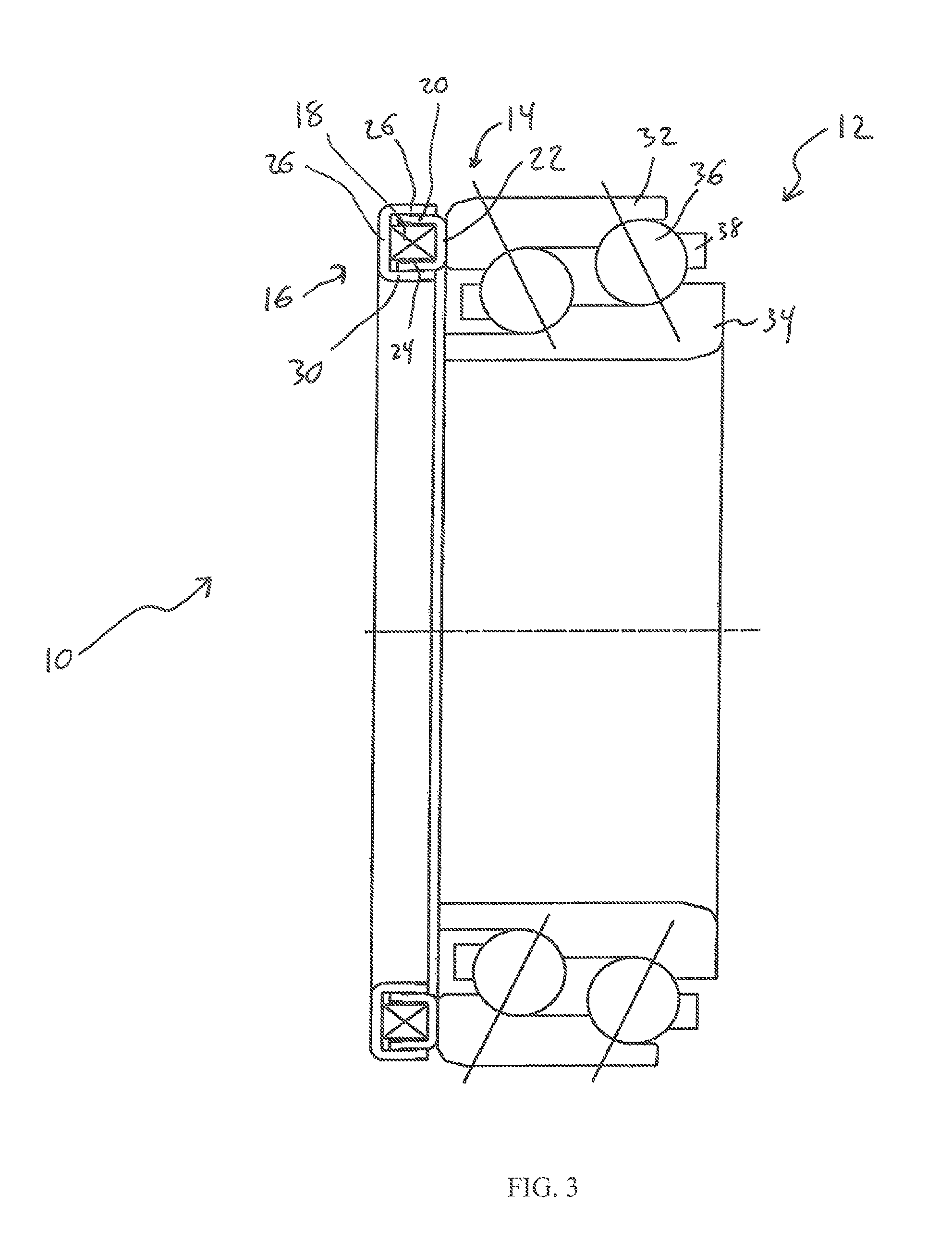
Thermal compensation element with wave spring
a wave spring and thermal compensation technology, applied in the direction of bearings, rigid supports of bearings, mechanical devices, etc., can solve the problems of loss of preload, etc., and achieve increased preload, increased frictional torque, and different thermal expansion coefficients
- Summary
- Abstract
- Description
- Claims
- Application Information
AI Technical Summary
Benefits of technology
Problems solved by technology
Method used
Image
Examples
first embodiment
[0038]FIG. 7 shows the thermal compensation element 100. As shown, a first wall 102 of the inner ring 104, which has a U-Shaped cross-section, has a first protrusion 106 and a second wall 108 of the inner ring 104 has a second protrusion 110. The first protrusion 106 is in sliding contact with an inner face of a first wall 112 of an outer ring 114 and the second protrusion 110 is in sliding contact with an inner face of a second wall 116 of the outer ring 114. Also, the first wall 112 of the outer ring 114, which has U-Shaped cross-section, is bent inward and is in sliding contact with an outer face of the first wall 102 of the inner ring 104 and the second wall 116 of the outer ring 114 is bent inward and is in sliding contact with an outer face of the second wall 110 of the inner ring 104. The configuration allows for axial movement of the inner ring 104 and the outer ring 114 to maintain a proper preload while ensuring the inner ring 104 and the outer ring 114 do not axially sepa...
second embodiment
[0039]FIG. 8 shows the thermal compensation element 200. As shown, a first wall 202 of an inner ring 204, which has U-Shaped cross-section, is bent outward and is in sliding contact with an inner face of a first wall 206 of an outer ring 208 and a second wall 210 of the inner ring 204 is bent outward and is in sliding contact with an inner face of a second wall 212 of the outer ring 208. Similarly, the first wall 206 of the outer ring 208, which also has a U-Shaped cross-section, is bent inward and is in sliding contact with an outer face of the first wall 202 of the inner ring 204 and the second wall 212 of the outer ring 208 is bent inward and is in sliding contact with an outer face of the second wall 219 of the inner ring 204. The configuration allows for axial movement of the inner ring 204 and the outer ring 208 to maintain a proper preload while ensuring the inner ring 204 and the outer ring 208 do not axially separate.
third embodiment
[0040]FIG. 9 shows the thermal compensation element 300. As shown, a groove 302 extends along an outer face of a first wall 304 of an inner ring 306, which has a U-Shaped cross-section, up to a first tab 308 which protrudes outward, toward a first wall 310 of an outer ring 312 and a groove 314 extends along an outer face of a second wall 316 of the inner ring 306, up to a second tab 318 which protrudes outward, toward a second wall 320 of the outer ring 312. Similarly, a groove 322 extends along an inner face of the first wall 310 of the outer ring 312, which also has a U-Shaped cross-section, up to a third tab 324 which protrudes inward, toward the first wall 304 of the inner ring 306 and a groove 326 extends along an inner face of the second wall 320 of the outer ring 312, up to a fourth tab 328 which protrudes inward, toward the second wall 316 of the inner ring 306. The first tab 308 and the second tab 318 are each in sliding contact with the grooves 322, 326, respectively, of o...
PUM
 Abstract
Description
Claims
Application Information
 - R&D
- Intellectual Property
- Life Sciences
- Materials
- Tech Scout
- Unparalleled Data Quality
- Higher Quality Content
- 60% Fewer Hallucinations
Browse by: Latest US Patents, China's latest patents, Technical Efficacy Thesaurus, Application Domain, Technology Topic, Popular Technical Reports.
© 2025 PatSnap. All rights reserved.Legal|Privacy policy|Modern Slavery Act Transparency Statement|Sitemap|About US| Contact US: help@patsnap.com


